7
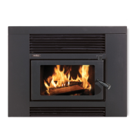
Position the Metro LTD Insert which is still attached to its
wooden pallet directly in front of the replace cavity with the
rear of the insert facing the replace opening. The replace
insert assembly is bolted to the wooden pallet through its base
panel at two points being each front corner. Remove both
screws and slide the insert into the replace cavity taking care
not to mark the oor protector. Discard the pallet.
1. Attach the fascia with the four longer screws that were
supplied in the plastic bag, taking care that the air control
lever passes through the slot provided in the fascia.
Centralise and level the fascia on the replace insert door
and secure the four screws.
2. Applying pressure to the door or inside the replace rebox
(not the fascia) carefully manoeuvre the Metro until the
rear of the fascia is just touching the front face of the
replace surround. Taking care not to move the replace
insert, remove the fascia and mark the position of the
replace insert onto the replace base.
3. Using a masonry drill, drill into the chimney base through
the two slots which the replace insert was secured to
the pallet through. Check to ensure the replace insert
hasn’t moved and secure using suitable masonry anchors
to comply with the seismic restraint provisions of the
standard.
4. Remove the top bafe from inside the replace insert and
the removable cabinet top. Check that the ue stub of the
replace insert is in line by looking down the chimney, if not
a stainless steel offset or exi ue will be required.
5. Following the instruction sheet supplied with the ue pack,
proceed and t the ue with all joints sealed and riveted
with a minimum of three stainless steel or monel rivets on
each joint.
6. With the ue pipe in position and sealed with a high
temperature re cement into the ue stub, drill through the
hole provided in the front of the ue stub into the stainless
steel ue pipe and secure with the 6mm bolt and nut
supplied in the plastic bag.
7. Ret the top bafe into the rebox’s upper chamber.
Reposition the removable cabinet top ensuring it is
correctly tting as detailed on page 2 and secure in its
upper position if possible. Note, if the adjustable height
top can be raised slightly but not fully to its upper position,
additional holes should be drilled to enable the top to be
raised to this level.
8. Using a suitable rated insulation (bretex 450 or similar)
pack any gap that exists between the sides and top of the
replace insert cabinet and replace surround.
9. Reattach the fascia, centralise and level with the door and
ensure the air control is moving freely and secure all four
screws.
10. Locate the air control knob which is included in the plastic
bag and carefully work it onto the air control lever.
The Metro is now fully installed and ready for operation but
it is preferable to defer lighting the re for a day or two if
possible to allow sealant used in the ue pipe joints to air dry.
Alternatively it is recommended you burn 2-3 sheets of loosely
crumpled newspaper at a time, approx once every hour over
a 6-8 hour period.
Installation