6
A
185mm
B
360mm
170mm
550mm
595mm
650mm
Refer
Chart
Firebox Model A B Width
LTD Insert 500mm 405mm 560mm
Fascia Model Base Width Body Width
Trend 810mm 810mm
Insert Raised LTD Insert
0mm 455mm insulated
10mm 455mm insulated
15mm 445mm insulated
20mm 436mm insulated
25mm 424mm insulated
30mm 408mm insulated
35mm 396mm insulated
40mm 366mm insulated
41mm & above 350mm insulated
45mm
50mm & above
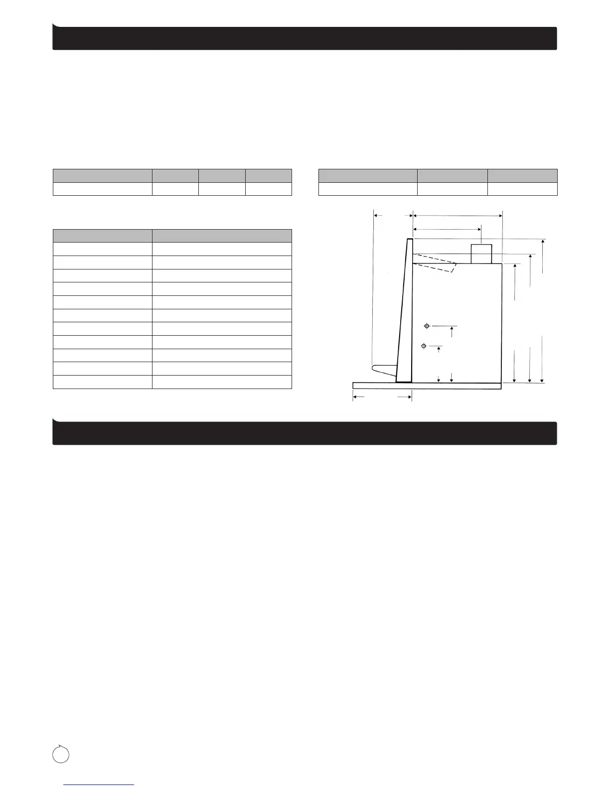
Minimum Floor Protector projection and type
Diagram 4
Floor protector requirements
Metro replace inserts are designed to be installed direct
onto a concrete base. An insulated oor protector is required
to project in front of the Metro and must extend a minimum
of 200mm to each side of the door opening, making the
minimum oor protector width 825mm. The minimum oor
protector projection forward of the Metro is dependant on the
height of the replace insert above the combustible oor. The
following schedule of oor protector projections is measured
from behind the Metro fascia being the total oor protector
depth as shown in Diagram 4 below. Note, the heights
specied above the combustible oor can be achieved by: -
• The thickness of the oor protector
• Or by raising the replace insert
• Or a combination of the two
Wetbacks
The Metro LTD Insert can be tted with either of Pioneer’s 3kW
or 4kW wetback option. Only Pioneer’s cast jacket wetback
system as illustrated on page 9 of this manual should be tted
to a Metro. Alternative wetbacks will void the Metro’s emission
approvals and may seriously effect the performance of the
appliance and will void the owners warranty.
Both 3kW and 4kW wetback options can be tted to either side
of the rebox, with the connection pipe heights illustrated in
Diagram 4 above, please note: -
• It is recommended the return pipe has a minimum rise of
1 in 12. Performance will reduce as the distance to the
storage cylinder increases.
• The wetback must be connected to a vented system. To t
the wetback proceed as follows: -
1. Remove the brick from the inside of the rebox from the
side the wetback is to be tted too.
2. Expose the holes in the rebox through which the
connection pipes will pass.
The LTD Insert has a 3mm pressed washer covering these
two openings and two 6mm bolts which are tted inside
the rebox near the connection holes, remove these also.
3. Using a hole saw or snips, prepare the cabinet for the
connection pipes. Note, these holes should be a neat
t or have any excess gap covered or lled with high
temperature insulation.
4. Using the tube of sealant supplied with the wetback, apply
a liberal bead of sealant around both connection holes on
the inside of the rebox. On the rear of the wetback casting
apply the remaining contents of the tube equally around
both connection pipes and also the outer circumference
of the wetback which will face the inside rear wall of the
rebox. This will completely seal the wetback to the inside
rear wall of the re on installation.
5. Fit the wetback into the rebox and position the connection
pipes through the connection holes in the rebox.
6.
Fit two bolts through the slots provided in the wetback, align
the wetback so its front edge is parallel to the door opening
& secure the bolts. The wetback is ready for connection to
the storage cylinder by a registered plumber.