2-3-1
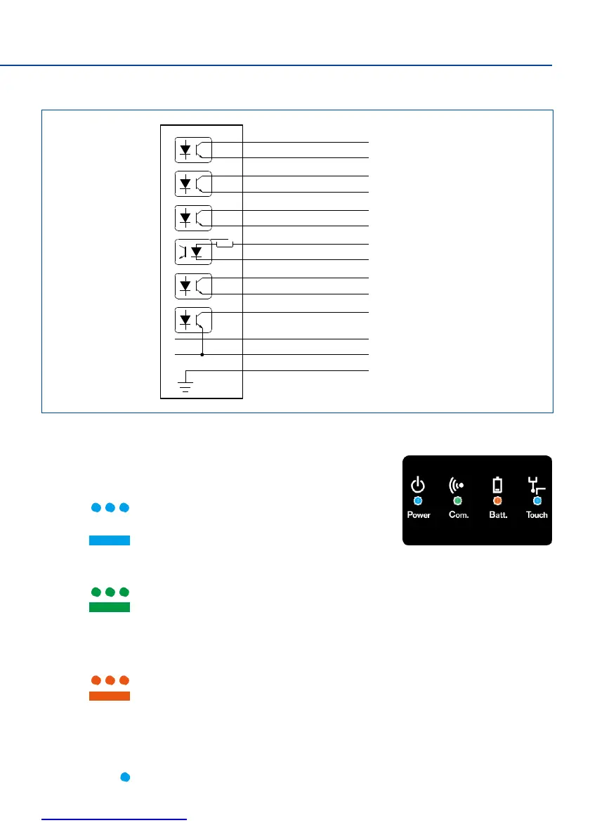
Wiring diagram
2-3-2
LED display
System status is displayed with four LED shown at right.
・Power LED :Indicates status of power supply.
:Standby (approxmately 60 seconds after
machine tool power is switched on)
:Normal power supply status
・Com. LED :Indicates communication status between transmitter and receiver.
:Communication status decreased or interrupted, or searching for connection
:Normal communication status
・Batt. LED :Indicates battery status of transmitter.
OFF :Battery normal
:Recommed replacing the battery
(
low residual charge
)
:Battery dead
*During the matching procedure, it indicates completion of matching mode (refer to P9)
・Touch LED :Indicates the signal output of the transmitter.
OFF:Contact OFF
(
transmitter signal output OFF
)
:Contact ON
(
touch probe signal output ON
)
BLUE
BLUE / BLACK
VIOLET
VIOLET / BLACK
GREEN
GREEN / BLACK
WHITE
BROWN
YELLOW
GRAY
ORANGE
+24V
PROBE STATUS 1
+24V
LOW BATTERY
+24V
ERROR
MACHINE START +
MACHINE START 0V
SKIP +
SKIP 0V
PROBE STATUS 2b
+24V
(
12V-30V
)
0V
MACHINE GROUND
 Loading...