- 6 -
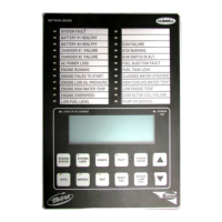
ENGINE TERMINAL (terminals 1-12) STATUS INDICATOR LIGHTS
Light Emitting Diodes (L.E.D.) lights have been installed above each engine wiring Terminal 1
through 12, except 11, to indicate the status of each terminal. Status indicator lights above
Terminals 6 and 8 should be on at all times when both batteries are connected. No light on
Terminals 6 or 8 indicates no battery power to that terminal. Status indication is given below:
Terminal Number L.E.D.(light) "ON" Indication
1 Power available to fuel and water solenoids
2 Speed switch has operated into crank disconnect mode
3 Speed switch has operated into overspeed mode
4 Oil Pressure switch contacts closed (Low Oil Pressure)
5 Water temperature switch contacts closed (High Engine Temperature)
6 Battery #1 voltage present
7 Battery and/or alternator voltage present
8 Battery #2 voltage present
9 Crank #1 voltage present (while cranking on #1 Battery)
10 Crank #2 voltage present (while cranking on #2 Battery
12 Energize to stop voltage present
1. BATTERY LOCKOUT TEST:
a. Turn on Battery #1 switch, Battery #1 light should be on.
b. Turn on Battery #2 switch, nothing should happen.
c. Press the "Battery Reset" button. Battery #2 lights should come on.
d. Turn Battery #1 switch off for a couple of seconds and back on. Battery #1 light
should go off and remain off.
e. Press "Battery Reset" button. Battery #1 light should come on.
2. CRANKING CYCLE TEST: This test simulates a condition where the engine refuses to
start.
a. Disconnect Terminal No.1 on Controller panel. NOTE:Disconnecting Terminal
No.1 is for the purpose of removing power from the fuel solenoid so engine
will not start. On engines where the fuel solenoid is not used (Caterpillar),
or is connected other than through Terminal #1 (Clarke-G.M.), other
means must be used to stop fuel flow to the engine to prevent starting.
b. Place control switch in "Test" position to crank engine. Time the crank and rest
periods, and count the number of cranks. There should be six (6) crank periods
separated by five (5) rest periods each of approximately 15-seconds duration. The
"Failed to Start" light should come on and the alarm bell should sound. Status
indicator light #1 should come on as soon as the selector switch is moved to
"Test" and pressure switch operates. Status lights 9 and 10 should come on
alternately to indicate cranking cycle.
c. Turn Control Switch to "Off" and properly reconnect all leads.
NOTE: In order to prevent discharging the starting batteries, this same test
can be made without actually cranking the engine by disconnecting
the starter cable and observing the action of the starter contactors
and/or status indicator lights 9 and 10.
3. CHECKING STARTING MOTOR RELEASE
a. Place control switch in "Test" position. Engine should start promptly and starting
motor should release at approximately 1/3 of engine speed. Status indicator light
#2 should come on to indicate speed switch has operated to disconnect cranking.
NOTE: A convenient method of determining the exact instant the starter
releases is to connect a battery test light or voltmeter across the
starter terminals and observe when power is disconnected.
b. Return Selector Switch to "Off" to stop engine.
 Loading...