- 3 -
PART I: GENERAL INFORMATION
The basic function of the model FD2 Fire Pump Controller for diesel engine driven fire pumps is to automatically start
the engine upon a drop in pressure in the water main, or from a number of other demand signals. This controller
provides automatic cycled cranking, alarm and/or alarm shutdown protection for various engine failures. Stopping of
the engine after the demand period is over may be either manual or automatic (Option R). This controller includes an
automatic weekly test starting feature. Numerous standard UL approved options may be provided.
PART II: FUNCTIONS
Equipment is provided in the Controller to provide the following functions:
A. Automatic Starting From:
a. Drop in water line pressure
b. Loss of battery charger output (Option P)
c. Operation of optional remote start switches, such as remote start switch, deluge valve
switch, fire alarm switch, etc.
d. Weekly test timer
B. Control Switch - A four (4) position switch is provided marked "Test-Auto-Off-Man".
C. Automatic Cranking - A solid state crank control provides six (6) fixed crank periods separated by
five (5) rest periods each of approximately 15 seconds duration.
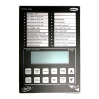
D. Alarms and Signal Lights - Eight (8) Standard lights are provided to give visual signals for "Failed
to Start", "Low Oil Pressure", "High Engine Temperature", "Charger or AC Failure",
control switch in "Auto" position, two (2) lights for "Batt 1, Batt 2", and "Overspeed". An
additional light for "Low Fuel" (Option F), and up to six (6) customer specified "Pump Room
Alarm" (Option K) can be provided. An audible alarm bell is mounted on the side of the cubicle for
sounding in the event of failure. Terminals are provided for remote failure indication of the
following:
"Selector Switch Position"
"System Failure"
"Engine Running"
"Battery Failure"
Option A provides customer selected alarm contacts for remote indication of each alarm.
E. A pressure recorder with a 7- day chart and battery operated chart drive is provided as standard.
F. A weekly test timer is supplied to automatically start the engine any set day of the week, at a set time
of day, and a preset run time.
G. "Stop" Pushbutton - A pushbutton is provided to stop the engine only after starting causes have
returned to normal. This returns the controller to the automatic position.
H. Integral Battery Chargers (Option J). Two separate automatic solid state chargers are supplied for
maintaining full charge on the dual sets of engine batteries. Charging current ammeters and battery
voltage voltmeters are included.
I. Cabinet - A heavy gauge steel cubicle encloses the controller. The lights, stop button, and meters are
mounted on the front of the cubicle. The control switch, battery circuit breakers, and manual start
pushbuttons are mounted behind a break-glass in the door of the cabinet.
PART III: OPERATION OF THE CONTROLLER
A. When the four (4) position control switch is in the "Auto" position and both circuit breakers are in
the
"On" position, the controller is in standby condition ready to start the engine automatically. A
 Loading...