- 4 -
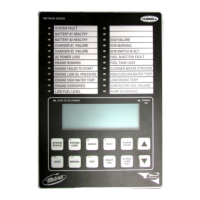
green pilot light marked "Auto" will illuminate in this position. Also, Battery No.1 and Battery
No.2 green lights will illuminate indicating that battery power is available. If both battery lights
are not on, verify that Battery 1 and Battery 2 circuit breakers are on, then press the “Battery
Reset” button.
When the water pressure drops below a level which is preset on the internal water pressure switch,
the pressure switch contacts will close, and the Controller will actuate the starter motor and the
cranking cycle will commence. If the engine starts and runs, cranking will cease and the protective
circuits will be operative. If the engine fails to start after six (6) crank periods, cranking will cease,
the "Failed to Start" light will light, and alarm bell will sound. The battery alternating circuit
alternates batteries on each crank attempt unless one battery is in a discharged state and incapable of
cranking the engine. In this instance, the control will lock onto the other battery for the remaining
cranking attempts. This non-operative battery locking circuit is reset by pushing the "Battery
Reset" pushbutton. Dry contacts for remote indication of "Battery Failure/Missing Battery" are
provided. After a “Failed to Start” failure, it is necessary to turn the control switch to
"Off" to reset.
The panel is wired so that optional remote start switches may be used, such as Deluge Valve
switches, Remote Start pushbutton, Fire Alarm switches, etc. In addition, when Option P is
provided, the Controller will automatically start the engine upon loss of Battery Charger output after
an adjustable time delay. The loss of charger light and bell are energized without delay.
While the engine is running, all protective circuits are operative. If the engine stops while running,
and there is still an auto start demand, the control will attempt to restart the engine. Failing in this,
the "Failed to Start" light will illuminate and alarm will sound. If, while the engine is operating,
the oil pressure drops below a safe limit, the “Low Oil Pressure” light will illuminate immediately.
After seven (7) seconds the alarm will sound. Should the engine temperature exceed a safe limit
while running the alarm will sound and the “High Water Temp.” light will illuminate to indicate
overheating.
In case of Overspeed, the engine will be stopped and the "Overspeed" light will illuminate and the
alarm will sound. The light and alarm will stay on until the Engine Speed Switch and the Controller
are manually reset. To manually reset the Controller, turn the Selector Switch to the "OFF"
position.
The Controller may be provided with either "Manual" or "Automatic" stop (Option R) as required.
"Manual" stop is provided as standard. A jumper must be removed between terminals 3T-1 and
3T-2 on the relay panel for an "Automatic" stop (Option R). With "Manual" stop, the engine will
continue to run even though the pressure switch or other remote starting switch returns to its normal
position. The engine can be stopped immediately only by pressing the stop button or moving the
control switch to "Off". If set up for "Automatic" stop, the engine will be stopped automatically
upon restoration to normal of whatever demand switch started the engine providing it has run at least
30 minutes, or for the period of time set on the Engine Run Timer (ERT). If the demand period was
less than the time set on the timer, the engine will continue to run until the timer times out and then
will stop.
B. When the control switch is in the "Test" position, the engine will be started by causing a drop in
water pressure. Failure circuits will be operative in the "Test" position. This method of starting
provides a test of the Controller, thereby assuring proper operation when required. The engine will
run continuously in this position until the switch is moved to "Off".
C. Placing the control switch in the "Off" position stops the engine when running, as explained in
preceding paragraphs. It also prevents the engine from starting when stopped. The switch should
always be placed in this position when servicing the engine or Controller.
D. The "Man"
position of the control switch is for manually starting the engine from either battery.
The fuel and water solenoids are energized in this position, and the engine must be cranked by
pushing one of the buttons above the control switch. "Manual Crank 1" cranks from Battery 1,
and "Manual Crank 2" cranks from Battery 2. Pressing both buttons will result in cranking from
both batteries simultaneously.
 Loading...