Do you have a question about the METRON FD4 and is the answer not in the manual?
Guides user through essential screens for controller setup, initiated by pressing a specific button.
Details various sources that trigger automatic engine start, such as pressure drops or remote switches.
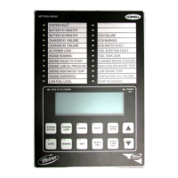
Describes the OID's role in displaying system data and enabling navigation for settings and alarms.
Explains the function of the selector switch for controlling the controller's operating mode.
Details the microprocessor-controlled crank cycle timer with fixed crank and rest periods.
Lists the twenty-two standard lights for visual signals of system status and potential failures.
Explains the feature that highlights the first alarm in a sequence for easier identification.
Explains controller standby and automatic engine start sequence upon pressure drop or other demand signals.
Describes how to initiate engine testing by simulating pressure drops, ensuring proper controller function.
Details manual engine starting via pushbuttons and the role of fuel/water solenoids.
Explains the timer-based feature for automatic engine test runs on a set schedule.
Covers provision for sequential pump starting using adjustable time delays on demand signals.
Indicates a command to start and run an additive pump controller due to a demand signal.
Annunciates loss of continuity in engine starting contactors, indicating a potential failure.
Indicates when both batteries are disconnected or turned off, with AC power still available.
Applies to electronic engines, signaling problems detected by the Electronic Engine Control Module.
Details factory assembly, wiring, and installer responsibilities for connecting engine components to the controller.
Outlines tests for control switch in 'Auto' mode and after installation to ensure proper operation.
Explains the LED indicators on the microprocessor module for each engine terminal status.
Procedure to test the battery lockout function by cycling battery switches and observing indicator lights.
Simulates an engine failing to start to test crank/rest periods and failed start indication.
Tests if the starting motor releases promptly at approximately 1/3 engine speed.
Tests the low oil pressure alarm and indicator light functionality.
Tests the high water temperature alarm and indicator light functionality.
Tests the engine overspeed alarm, indicator lights, and engine stop function.
Tests the contactor coil failure alarm by simulating a loss of continuity.
Verifies automatic engine start based on pressure drops or other demand switches in Auto mode.
Checks the weekly test start function by verifying engine starts and runs at a preset time.
Guides on setting the weekly test start time and duration via configuration screens.
Details wiring terminals for remote start switches like pushbuttons and deluge valves.
Tests the controller's ability to start the engine automatically upon AC power loss.
Explains automatic mode, engine start on demand, and automatic/manual stopping.
Covers timers for sequential starting in multiple pump installations.
Describes field terminals for various pump room alarms and their silencing.
Details an optional feature to operate an external pressure dump valve for Foam Pump Service.
Explains the automatic battery chargers, monitoring, and troubleshooting for charger issues.
Describes common OID operations like silencing horns, resetting alarms, and entering test mode.
Identifies buttons for system operation and control, including Auto, Manual, and Test modes.
Explains the digital display and navigation buttons for interacting with the controller interface.
Adjusts conditions for starting and stopping the engine, requiring Level 1 password.
Adjusts settings not directly related to engine operation, requiring Level 1 password.
Factory/technician settings for fine-tuning special systems, requiring Level 2 password.
Calibrates analog pressure and battery volt readings, requiring Level 2 password.
Sets up user programs for monitoring auxiliary signals, requiring Level 2 password.
Provides a step-by-step guide on how to navigate and modify set point values within the configuration screens.
Sets the pressure threshold for automatic engine start in Auto mode. Should be lower than stop pressure.
Sets the pressure threshold for stopping the engine in Auto mode or allowing manual stop.
Delays engine start in Auto mode upon low pressure or deluge valve signal, useful for pump sequencing.
Enables automatic engine stop after all demands are satisfied and minimum run time is met.
Specifies the minimum engine run duration before automatic stopping, per NFPA 20.
Enables weekly automatic engine test runs at a preset day and time.
Sets the specific day of the week for the automatic weekly engine test to commence.
Sets the specific time of day for the automatic weekly engine test to begin.
Defines the duration the engine will run during an automatic weekly test.
Enables engine shutdown on low oil pressure or high water temp during weekly test runs.
Enables automatic engine start when AC power is lost, with a delay to override outages.
Sets the delay time for starting the engine after AC power loss to override momentary outages.
Enables engine start if a faulty pressure transducer is detected or max voltage is sensed.
Used for external signal of a secondary failed to start alarm.
Selects whether the low intake shutdown contact is Normally Open (NO) or Normally Close (NC).
Enables low suction shutdown if a separate suction pressure switch is connected.
Sets a timer to override momentary dips in suction pressure before a shutdown occurs.
Clears the low intake alarm automatically if the condition clears for the set reset time.
Sets the time low intake pressure condition must clear for automatic alarm reset.
Monitors an optional pressure switch closure to start the engine on low pressure in Auto mode.
Monitors an optional deluge valve switch opening to start the engine in Auto mode.
Determines pressure at which High System Pressure variable is turned on, used for variable speed applications.
Determines if engine lockout input requires momentary contact to stop or prevent starting.
Selects whether the remote start contact is Normally Open (NO) or Normally Close (NC).
Guides on setting system real time, date, day of week, and logging preferences.
Sets the current 24-hour clock for the FD4 controller.
Sets the current date for the FD4 controller.
Sets the local day of the week for the FD4 controller.
Enables logging of current system pressure when it drops below a set pressure value.
Sets the desired pressure that triggers a log of system pressure when it drops.
Sets the time pressure must be above the trip pressure for the event to be logged as cleared.
Sets the frequency for automatic system pressure logging.
Enables or disables the remote keypad functionality for controller interaction.
Sets the LCD backlight to always on or power save mode.
Allows selection between English or Spanish language for the controller display.
Sets the password required to access system configuration screens.
Saves auxiliary alarm configuration parameters to the SD card.
Loads auxiliary alarm configuration parameters from the SD card.
Selects display units for pressure: psi, bar, or kg/cm2.
Selects whether the charger failure alarm is active while the engine is running.
Sets the delay before the controller signals a charger failure alarm after contacts close.
Sets the Modbus address for communication when Modbus is enabled.
Enables Modbus protocol via RS485 and disables ASCII text output for the printer.
Sets the baud rate for Modbus or Printer communication.
Sets the parity for Modbus communication (Even, Odd, or None).
Restarts Wifi communication for the controller.
Describes the comma-delimited format for daily pressure log files stored on the SD card.
Describes the comma-delimited format for event log files stored on the SD card.
Specifies the storage capacity for events and pressure logs on the SD card.
Explains the procedure for removing the SD card and the resulting system messages and alarms.
Details how the controller detects and reacts to SD card logging errors.
Lists and describes files like EVENTS.TXT, CONFIG.TXT, and PRESS**.TXT stored on the SD card.
Explains how pressure logs are created and managed on the SD card with specific file naming conventions.
Explains how event logs are created and managed on the SD card with specific file naming conventions.
Guides on configuring Modbus settings like address, baud rate, and parity through controller screens.
Explains access and control of historical logs and real-time clock via Modbus registers.
Describes viewing real-time events via Modbus register 40002 and its 16-bit breakdown.
Lists Modbus registers (40002, 40003, 40004) and their descriptions for real-time event monitoring.
Lists Modbus registers (40005, 40006) and their descriptions for system relay status.
Explains how to set and read the controller's real-time clock using Modbus registers.
Lists Modbus registers for reading miscellaneous data like battery voltage, amperage, and run hours.
Explains viewing historical events and alarms via Modbus registers and setting log pointers.
Lists event and alarm descriptions with corresponding index numbers for historical logging.
Continues the list of event and alarm descriptions with index numbers for historical logging.
Explains viewing historical pressure readings via Modbus registers and scrolling through the log.
Lists Modbus registers for PSI historical log index, pressure, and date/time stamp information.
| Category | Controller |
|---|---|
| Input Voltage | 24 VDC |
| Number of Channels | 4 |
| Protection Class | IP20 |
| Output Current | 4 A |
| Weight | 0.2 kg |