Do you have a question about the METRON MP430 Series and is the answer not in the manual?
Covers MP430/MP435 operation, OID, and alarm indicators.
Details the continuous pressure recording system and its storage.
Details the system event logging capability and storage.
Details the alarm log as a subset of the event log.
Optional space heater for moisture reduction in the cabinet.
Option for automatic weekly motor run tests.
Option to omit controller legs for common skid mounting.
Optional dot matrix printer for log data.
Available NEMA type enclosures for the controller.
Overall conformance to standards and voltage availability.
Lists standard controller features like enclosure, OID, and indicators.
Details standard auxiliary inputs/outputs and programmable alarms.
Covers standard pressure, event, and alarm logs.
Lists standard optional features available.
Lists methods for automatic pump starting.
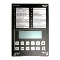
Describes the OID's display, buttons, and navigation.
Details standard indicator lights and audible alarm functions.
Explains the data logging capabilities for system events.
Describes the automatic weekly test feature.
Explains the function of the manual start and stop buttons.
Describes the physical enclosure of the controller.
Details auto mode, starting sequence, and stop conditions.
Explains how the test mode initiates pump starts.
Describes the weekly test timer operation.
Explains how sequential starting is achieved.
Details the use of the emergency manual start lever.
Explains the Series MP400 primary resistance start.
Describes how the controller starts on AC power loss.
Details automatic pump start/stop logic.
Explains the timer for multiple pump installations.
Details inputs for pump room alarm monitoring.
Guidelines for installing the fire pump controller.
Outlines tests to perform after installation for proper operation.
Explains the status indicators (LEDs) for inputs and outputs.
Details tests for automatic pump starting.
Describes the procedure for the weekly pump test.
Explains how to set the weekly test schedule.
Details wiring for remote start switches.
Introduces the OID, its LEDs, buttons, and display.
Covers horn silencing, alarm resetting, mode changes, test, and lamp test.
Explains how to navigate between system status, logs, and config menus.
Details navigation through system status, logs, and configuration menus.
Explains how to navigate configuration setpoint screens.
Describes navigation within system status and system logs screens.
Explains the three data logs: alarm, event, and pressure.
Details how to navigate and view entries in the logs.
Explains how to print data from alarm, event, and pressure logs.
Describes the structure of configuration screens and password protection.
Details the process of modifying configuration setpoints.
Explains how to print configuration setpoint data.
Defines settings for pump start and stop pressure.
Defines settings for start delay and automatic stopping.
Defines settings for ramp stop and solenoid drain valve.
Defines settings for automatic weekly test operation.
Defines the duration for automatic weekly test runs.
Defines whether to stop the pump during tests if an alarm occurs.
Defines settings related to supervisory power monitoring and startup.
Defines if the pump starts on pressure transducer failure.
Defines settings for shutdown on low intake pressure or level.
Defines if the pump starts via a connected pressure switch.
Defines the setting to monitor the deluge valve for pump start.
Defines various user preference settings for the controller.
Defines settings for high and low discharge pressure alarms.
Defines no load conditions and LCD backlight settings.
Defines language selection and user password settings.
Defines the setting to correct phase reversal indications.
Lists and explains possible messages in alarm and event logs.
Lists text messages for auxiliary alarms and internal variables.
Describes the printer's buttons and basic operation.
Details how to operate the door latch and paper feed button.
Guides on how to replace the paper roll in the printer.
Guides on how to replace the printer ribbon cartridge.
| Category | Controller |
|---|---|
| Series | MP430 |
| Input Voltage | 24V DC |
| Output Voltage | 0-10V DC |
| Protection Class | IP20 |
| Weight | 200g |