This document describes the METRON Model FD2 Fire Pump Controller, designed for diesel engine-driven fire pumps. Its primary function is to automatically start the engine when a drop in water main pressure or other demand signals occur. The controller incorporates automatic cycled cranking, alarm, and/or alarm shutdown protection for various engine failures. It also features an automatic weekly test starting capability and supports numerous standard UL-approved options.
Function Description
The FD2 controller provides several key functions to ensure reliable fire pump operation:
Automatic Starting: The engine can be started automatically due to:
- A drop in water line pressure.
- Loss of battery charger output (Option P), with an adjustable time delay.
- Operation of optional remote start switches, such as deluge valve switches or fire alarm switches.
- A weekly test timer.
Control Switch: A four-position control switch is provided, labeled "Test-Auto-Off-Man," allowing for different operational modes.
Automatic Cranking: A solid-state crank control manages six fixed crank periods, each separated by approximately 15-second rest periods. The battery alternating circuit switches between Battery 1 and Battery 2 for each crank attempt. If one battery is discharged, the control locks onto the operative battery for remaining attempts. This non-operative battery locking circuit can be reset by pressing the "Battery Reset" pushbutton.
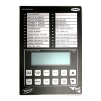
Alarms and Signal Lights: Eight standard lights provide visual signals for "Failed to Start," "Low Oil Pressure," "High Engine Temperature," "Charger or AC Failure," "Batt 1," "Batt 2," and "Overspeed." Additional lights can be provided for "Low Fuel" (Option F) and up to six customer-specified "Pump Room Alarm" (Option K) indications. An audible alarm bell is mounted on the cubicle side for sounding during failures. Terminals are available for remote failure indications, including "Selector Switch Position," "System Failure," "Engine Running," and "Battery Failure." Option A allows for customer-selected alarm contacts for remote indication of each alarm.
Pressure Recorder: A 7-day chart pressure recorder with a battery-operated chart drive is standard, providing a permanent record of water main pressure fluctuations and engine starts.
Weekly Test Timer: This timer automatically starts the engine on a set day and time, running it for a preset duration.
Stop Pushbutton: A pushbutton is provided to stop the engine only after starting causes have returned to normal, returning the controller to the automatic position.
Integral Battery Chargers (Option J): Two separate automatic solid-state chargers maintain full charge on the dual sets of engine batteries. Charging current ammeters and battery voltage voltmeters are included.
Cabinet: The controller is enclosed in a heavy-gauge steel cubicle. Lights, the stop button, and meters are mounted on the front. The control switch, battery circuit breakers, and manual start pushbuttons are located behind a break-glass in the cabinet door.
Usage Features
Automatic Operation ("Auto" Position):
- The "Auto" green pilot light illuminates, along with "Battery No.1" and "Battery No.2" green lights, indicating available battery power. If battery lights are off, verify circuit breakers are on and press "Battery Reset."
- The controller automatically starts the engine when water pressure drops below a preset level, a remote start switch is activated, or the weekly test timer initiates a start.
- During engine operation, all protective circuits are active. If the engine stops while an auto start demand exists, the controller attempts to restart. Failure to restart triggers the "Failed to Start" light and alarm.
- "Low Oil Pressure" light illuminates immediately if oil pressure drops below a safe limit, followed by an alarm after seven seconds.
- "High Water Temp." light illuminates and an alarm sounds if engine temperature exceeds a safe limit.
- In case of overspeed, the engine stops, the "Overspeed" light illuminates, and an alarm sounds. This requires manual reset by turning the selector switch to "Off."
- The controller can be configured for "Manual" or "Automatic" stop (Option R). With "Manual" stop, the engine runs until manually stopped. With "Automatic" stop, the engine stops automatically after the demand signal ceases, provided it has run for at least 30 minutes or the preset Engine Run Timer (ERT) duration.
Test Operation ("Test" Position):
- The engine starts by simulating a drop in water pressure.
- Failure circuits remain operative during test runs, ensuring proper controller function.
- The engine runs continuously until the switch is moved to "Off."
Off Position:
- Stops the engine if running.
- Prevents the engine from starting.
- Recommended for servicing the engine or controller.
Manual Operation ("Man" Position):
- Disconnects all automatic start circuits.
- Allows manual starting from either battery by pressing "Manual Crank 1" (Battery 1) or "Manual Crank 2" (Battery 2) pushbuttons. Pressing both cranks from both batteries simultaneously.
- Fuel and water solenoids are energized.
- All alarms remain functional.
- The engine runs until the selector switch is turned to "Off."
Periodic Self Testing:
- The program clock can be set for test runs on any day and time.
- A timing element ensures the engine runs for a definite time (minimum 30 minutes) before shutting down.
Sequential Starting (Option S):
- Adjustable time delay relays prevent multiple pumps from starting simultaneously.
- Timers are set progressively longer for subsequent pumps.
- Failure of the lead pump does not prevent subsequent pumps from starting.
Remote Start Switch Circuits:
- Terminals #15 and #16 are for remote manual start pushbuttons (close to start).
- Terminals #13 and #14 are for remote automatic start switches (open to start), such as deluge valve switches. A jumper is installed between #13 and #14 if no deluge switch is used.
Power Failure Starting (Option P):
- Automatically starts the engine after a time delay upon loss of battery charger output (120 VAC).
- The "Charger or AC Failure" lamp illuminates, and an alarm sounds without delay.
Low Fuel Supply (Option F):
- Field terminals are provided for low fuel level contacts.
- An alarm sounds, and the "Low Fuel" light illuminates when low fuel contacts close.
- The alarm cannot be silenced until fuel is added to the tank.
Pump Room Alarms (Option K):
- Field terminals are provided for various pump room alarm inputs (e.g., Low Fuel, Low Pump Room Temperature, Reservoir Low/Empty, Low Suction Pressure, Relief Valve Discharge, Flow Meter On).
- An alarm sounds, and a light illuminates when alarm sensor contacts close.
- These alarms can be silenced with a pushbutton on the controller.
Engine Lockout (Option E):
- Relay 19CR, when energized, prevents the engine from starting or stops it if running.
- Useful for two-pump systems or low suction pressure conditions.
- Can be overridden by placing the selector switch in "Man" and pressing "Manual Crank" buttons.
Energize to Stop:
- For engines with normally open fuel solenoids that must be closed to stop (e.g., Caterpillar engines).
- 1T Terminal 12 is hot (battery power applied) at all times except when the engine is running.
Remote Alarm Contacts:
- 1T Terminals 17, 18, 19 provide contacts for remote indication that the switch is not in "Auto."
- 1T Terminals 20-25 provide two sets of "Engine Running" contacts for remote indications or other control functions.
- 1T Terminals 26-28 provide contacts for remote indication of a system failure.
- 1T Terminals 29-31 provide contacts for remote indication of battery failure.
- 1T Terminals 34-41 provide an alarm signal for low fuel level (Option F) or pump room alarms (Option K).
Individual Alarm Contacts (Option A):
- Contacts for individual indication of each alarm condition, along with customer-specified alarms, can be provided by Relays 51CR through 60CR and one pole of 15CR and 18CR. These contacts are wired to 1T Terminals 51 through 86.
Maintenance Features
Troubleshooting Hints:
- General: Ensure all relays are firmly seated, and status lights 6, 7, and 8 are on.
- Engine Refuses to Crank: Check status lights 9 and 10. If they operate, the problem is in the engine or wiring. If not, check speed switch, crank relay (7CR), engine running relay (9CR), auto start relay (8CR), battery charge, and connections.
- Engine Cranks but Does Not Start: Check status light #1 (Fuel Solenoid Relay 6CR). If not, 6CR may be defective. On "Energize to stop" engines, check status light #12 is "Off." Check fuel solenoid. If cranking doesn't stop and "Failed to Start" signal doesn't come on, check Solid State Crank Control.
- Engine Starts but Starter Does Not Release: Check status light #2. It should be off during cranking and come on before the engine reaches 1/2 normal speed. Check speed switch and engine running relay (9CR). Check starter contacts for welding.
- Engine Will Not Start on Weekly Test Runs: Ensure the clock is set correctly. Operate the program clock to "On" and check if the drain valve operates. If the drain valve operates but the engine doesn't start, check the pressure switch and auto start relay 8CR.
- Engine Will Not Stop on Test Runs or Starts Every Time Control Switch is Placed in "Auto": Stop the engine by turning the control switch to "Off." Check pressure switch contacts, other demand switches, and program clock status. If remote start switches are wired, ensure their positions are correct or a jumper is installed between terminals #13 and #14.
- Low Oil Pressure Alarm Does Not Operate: In "Auto," short the oil pressure switch. Check if the "Low Oil Pressure" light illuminates and the alarm sounds after seven seconds. If the light doesn't illuminate but status light #4 comes on, the problem is in the controller. If status light #4 doesn't come on, the problem is in the engine or wiring.
- High Engine Temperature Alarm Does Not Operate: In "Auto" with the engine running, short the temperature switch terminals. Check if the "High Engine Temperature" light and/or alarm come on and status light #5 comes on. If not, the problem is in the engine or wiring. If operation is correct on this test but not under actual conditions, replace the water switch.
- Overspeed Alarm and Shutdown Does Not Operate: Momentarily short the speed switch terminals. If status light #3 is on but the engine doesn't shut down and the alarm doesn't operate, the problem is in the controller. If status light #3 doesn't come on, the problem is in the engine or wiring. If the engine stops and the light/alarm operate on this test but not under actual conditions, replace the overspeed switch. If the controller is at fault, check relay 15CR, diode D46, D47, or D49.
- Circuit Breaker in Controller Tripped: Check for sticking voltage regulator, engine generator/alternator charging above 20 amperes (for older engines), external short circuits, and status lights.
- Loss of Battery Charger Output: Check AC voltage to charger, charger fuses, connections, and refer to the separate NRG charger manual for troubleshooting.
Batteries/Battery Charger:
- Inspection: Daily for a few days after installation, then weekly. Check electrolyte level, location, ventilation, cable size, and electrical/mechanical connections.
- Charger Connection: Ensure the integral battery charger is connected to proper 120 VAC supply voltage, preferably with an external 20-amp circuit breaker/disconnect.
- Charging Performance: Ammeters should show a high charge rate (10-15 amps/meter) initially, gradually decreasing as batteries charge. Voltmeters should indicate proper 12/24 VDC.
- Battery Condition: Check for overcharging (gassing) or undercharging (low voltage, low specific gravity).
- Electrolyte: Only distilled water should be added to batteries. Never add new electrolyte (acid) to a previously filled battery.
- Charger Faults: If a battery is not connected, the battery fault light on the charger, charger failure lamp on the controller, and audible alarm will be on. The appropriate battery light will also go out.
- Separate Manual: Refer to the separate Installation and Operation Manual for the Battery Charger for specific operation and troubleshooting instructions.