SECTION 4 - COUNTERSHAFT, CTRSHAFT BOX & SHEAVE ASSEMBLIES
4-6
MP SERIES CONE CRUSHER TECHNICAL REFERENCE MANUAL
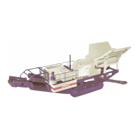
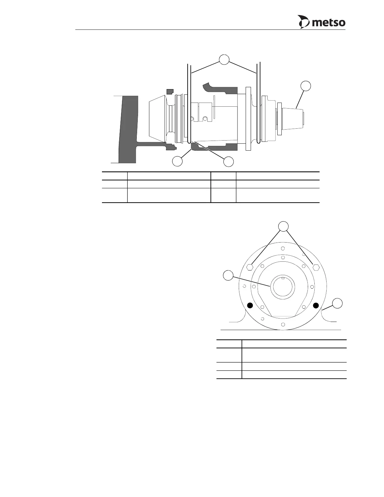
Figure 4-5 Installing Countershaft Box Assembly
7. Lower the pinion end of the countershaft
box, again making sure the countershaft box
centering lug rests on the main frame guide
support.
8. Insert two M42 x 220 LG, for the MP1000,
or M36 x 220 LG for the MP800 hex head
pull-in capscrews into the tapped holes in
the main frame at the position shown in
Figure 4-6. These pull-in capscrews are part
of the tools that came with the Crusher.
9. Alternately tighten each pull-in capscrew a
small amount, to prevent binding, until there
is a 50 mm (2.0") gap between box flange
and main frame as shown in View 2 of
Figure 4-7.
10. Remove the two pull-in capscrews and place
spacers or a stack of washers, 50 mm (2.0")
thick onto the capscrews. Reinstall them into
the frame. Again alternately tighten each
bolt until a 20 mm (0.75") space between the
countershaft box flange and main frame is
obtained as shown in Views 3 and 4,
Figure 4-7.
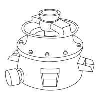
Figure 4-6 Countershaft Box Pull-In Capscrew
Placement
Callout Description Callout Description
1 Lifting slings 3 Countershaft box centering lug
2
Sheave bushing (or set collar,
direct drive)
4 Frame support guide
1
2
4
3
Callout Description
1
Place countershaft box pull-in capscrews
in locations shown
2 Countershaft box flange
3 Oil flinger housing
1
2
3