Slurry Pump
WH18AA11D00EN_01G.DOC JAN 04-W08
Care and maintenance
1/4
9.5.2 Hydraulic parts and frame - dismantling and fitting
(i) Opening and closing the pump – fixed base
WARNING
MAKE SURE THAT ALL SLINGS, SHACKLES, ETC. ARE OF ADEQUATE LOAD CARRYING CAPACITY.
APPROXIMATE WEIGHTS OF MAJOR COMPONENTS ARE PROVIDED IN SUB-SECTION 11.3.
LIFTING POINTS INCORPORATED IN INDIVIDUAL COMPONENTS ARE INTENDED SOLELY FOR LIFTING
THAT SPECIFIC COMPONENT. NEVER USE THESE FOR LIFTING ASSEMBLIES OF COMPONENTS.
1. General
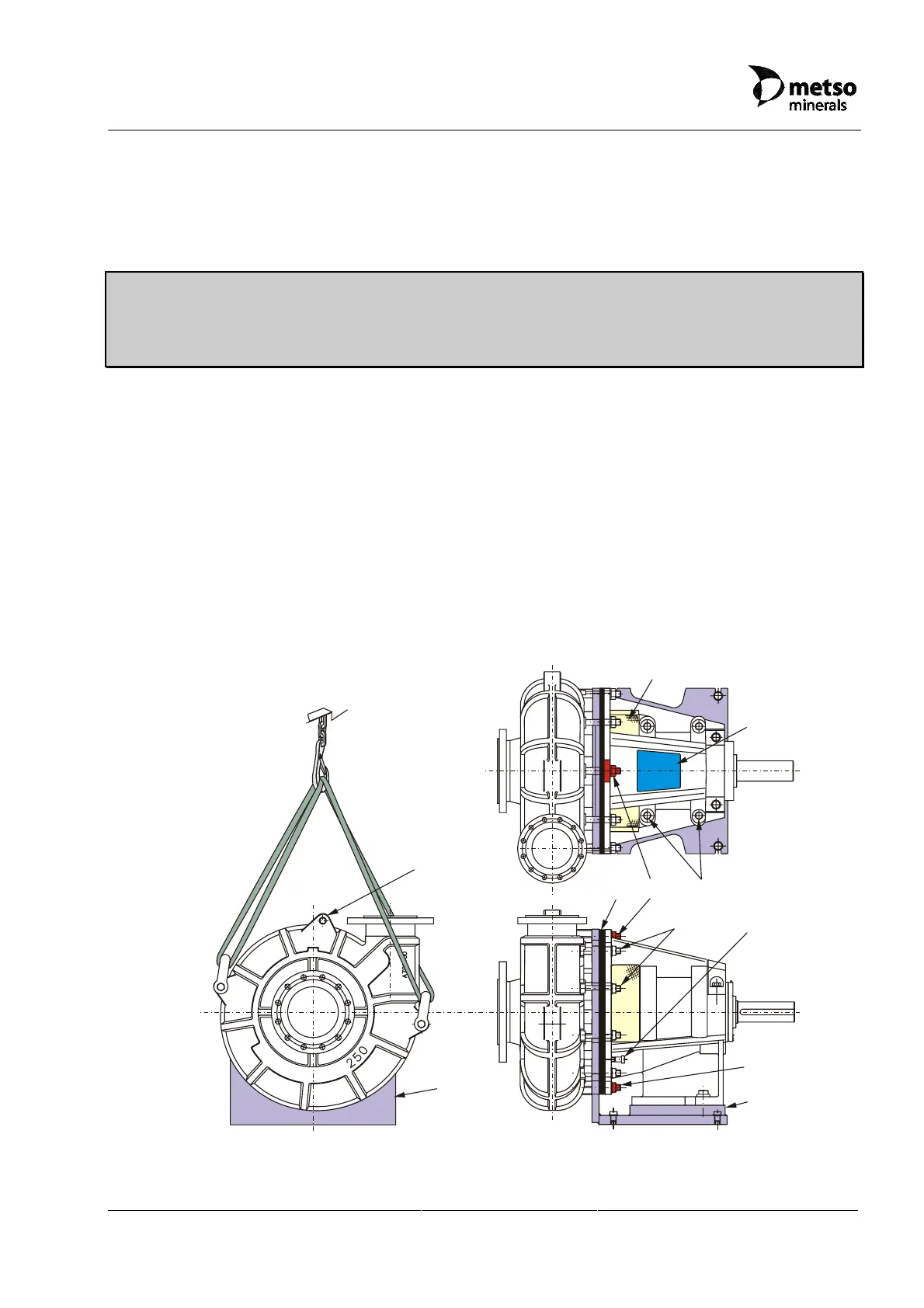
The base (L) supports the case, the bearing and the rotating assemblies. See Figure
9.5.2-1. Bosses (D) cast in the frame are used to mount the drive motor overhead, if
required.
Slots in the base vertical plate provide locations for case fixings (B). The top and bottom
dead centre holes in the vertical plate are for the case clamp fixings (C). This method of
attachment allows the case to be installed with the outlet in a number of positions - see
‘General Arrangement’, section 2.6.
L
C
B
D
E
F
G
L
C
H
P
Figure 9.5.2-1 Bareshaft pump (typical)
 Loading...