Slurry Pump
WH18AM12AA0EN_01F.DOC JAN 04-W08
Care and maintenance
1/2
9.5.2 Hydraulic parts and frame - dismantling and fitting
(ii) Wet-end - disassembly and reassembly
1. General
Case (W1), impeller (W3) and back-liner (W4) are high quality, high-chrome iron castings.
Larger size pump cases are ribbed and incorporate a number of lifting lugs. The inlet and
outlet branches are fitted with joint seals (F2, F4) and split flanges (F1, F3) to provide a
leak-proof and secure pipework connection.
The back-liner, which forms the rear face of the case, is attached to bearing frame (P14)
by tee bolts (W19) and hexagon-headed nuts (W20). For ease of assembly, the bolts are
retained in the slots by means of a rubber strap (W18). O-rings (W6) are used to seal the
back liner and the case.
The wide choice of impellers available permit the most efficient case-impeller combination
to be adopted for each application.
2. Removing impeller (W3) and back-liner (W4)
a) If an impeller release mechanism is fitted refer to section 9.5.2 (iii); otherwise,
insert a suitable bar between two impeller vanes and lock the bar against a
suitable static object. Apply a shock load by turning shaft (B11) in a direction
opposite to the pump rotation. Alternatively, lock the shaft and shock the
impeller. Sub-section 2.1.2 identifies the direction of rotation of the pump during
operation.
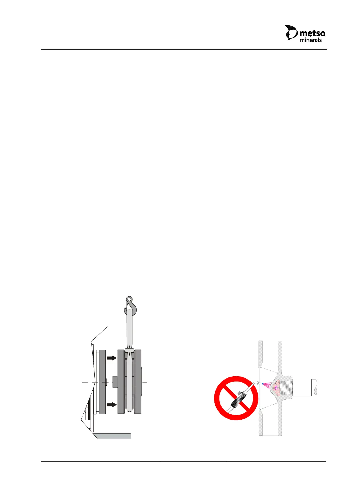
b) Steady and suitably support impeller (W3) as it moves off shaft (B11).
Figure 9.5.2-A Removing impeller (W3)
DANGER OF
EXPLOSION
DO NOT
APPLY
HEAT
Figure 9.5.2-B Do not apply heat in order
to remove the impeller
 Loading...