CHAPTER 2: GALAXY ENCLOSURES AND I/O
22
• Wink Button: Pressing the Wink button on the rear of a GALAXY processor will cause the device to enter the Identify
Mode, a bidirectional processor identification feature that helps users locate processors in multi-processor
configurations. The front panel will flash, and Compass will show an indication on both the GALAXY processor’s
Inventory tab and the Settings > Network tab of each processor (“Settings Tab” on page 34). To exit Identify Mode, push
the Wink button on the processor again or click on the Identify button on the Network tab in Compass.
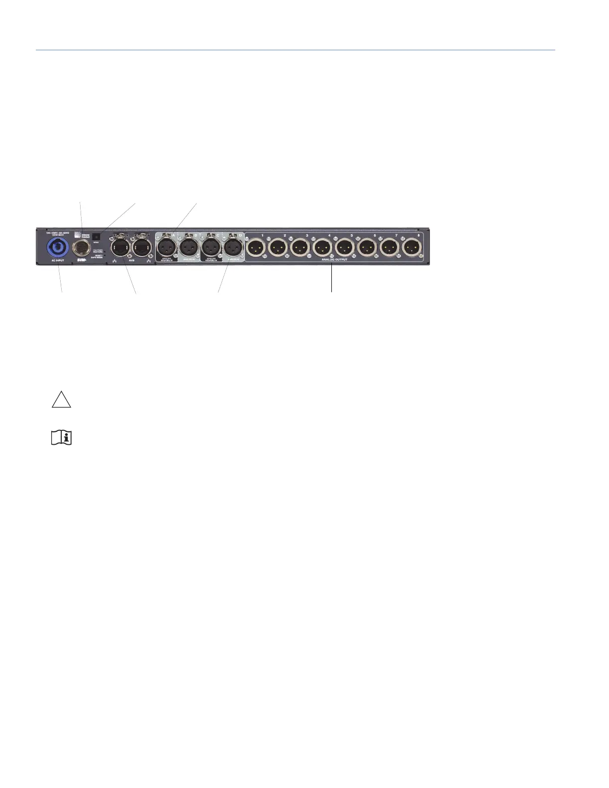
GALAXY 408 Processor Rear Panel Connectors
The GALAXY 408 processor rear panel provides the following connectors:
• PowerCON AC Power Connector: This locking connector mates with the provided AC power cable.
CAUTION: Make sure the AC power cable has the appropriate power plug on the other end for the area in
which you will operate the GALAXY.
NOTE: The GALAXY processor incorporates Meyer Sound’s Intelligent AC power supply, which automatically
adjusts to any line voltage worldwide, and provides soft turn-on and transient protection.
• Ethernet Connector: The two RJ-45 connectors can be used to attach the GALAXY processor to an AVB network to
send audio signals through time-sensitive networks, and allow it to be controlled by Compass and/or Compass Go. Use
a Giga-bit Ethernet network cable (CAT5e or better).
• Analog /AES Input Connectors (A, C): Two XLR-3F input connectors accept either a standard line-level analog signal
or an AES two-channel digital signal. In Compass (Settings > Input and Output), these inputs can be set to Analog, AES3
Left or AES3 Right. Input Connectors B and D can only be used as analog inputs. The GALAXY processor supports
standard AES3 digital audio signals at discrete sample rates in the range of 20–216 kHz (see “Input Sample Rates” on
page 62).
• Analog Input Connectors (B, D): Two XLR-3F input connectors accept standard line-level audio only. These inputs are
typically paired with their corresponding input pairs (A, C) to receive two-channel audio signals. The analog-only inputs
are disabled when their input pair is set to AES mode (i.e., when input A is set to AES mode, input B is disabled).
• Analog Output Connectors (1–8): Eight XLR-3M connectors route audio to Meyer Sound self-powered loudspeakers,
or to amplifier channels driving passive systems.
• SIM 3 Bus Connector: Connects to the SIM audio analyzer so the GALAXY’s inputs and outputs can be used as
measurement points.
Figure 6: GALAXY 408 Processor Rear Panel
Analog/AES Input
Connectors
SIM 3 Bus
Connector
PowerCON
AC Power
Connector
Analog Output
Connectors
Ethernet
Connectors
Wink
Button
Analog Input
Connectors
 Loading...