LYON OPERATING INSTRUCTIONS
16
Pins 2 and 3 carry the input as a differential signal. Pin 1 is
connected to earth through a 1 kOhm, 1000 pF, 15 V
clamped network. This circuitry provides virtual ground lift for
audio frequencies while allowing unwanted signals to bleed to
ground. Make sure to use balanced XLR audio cables with
pins 1–3 connected on both ends. Telescopic grounding is
not recommended and shorting an input connector pin to the
case may cause a ground loop, resulting in hum.
TIP: If unwanted noise or hiss is produced by the
loudspeaker, disconnect its input cable. If the
noise stops, there is most likely nothing wrong with the
loudspeaker. To locate the source of the noise, check
the audio cable, source audio, AC power, and electri-
cal ground.
Audio Loop Output (XLR 3-Pin or 5-Pin Male)
The XLR 3-pin or 5-pin male Loop output connector allows
multiple loudspeakers to be looped from a single audio
source. The Loop output connector uses the same wiring
scheme as the Input connector (see “Audio Input (XLR 3-Pin
or 5-Pin Female)” on page 15). For applications that require
multiple LYONs, connect the Loop output of the first
loudspeaker to the Input of the second loudspeaker, and so
forth.
NOTE: The Loop output connector is wired in
parallel to the Input connector and transmits
the unbuffered source signal even when the loud-
speaker is powered off.
Calculating Load Impedance for Looped Audio
Signals
To avoid distortion when looping multiple loudspeakers,
make sure the source device can drive the total load
impedance of the looped loudspeakers. In addition, the
source device must be capable of delivering approximately
20 dBV (10 V rms into 600 ohms) to yield the maximum SPL
over the operating bandwidth of the loudspeakers.
To calculate the load impedance for the looped
loudspeakers, divide 10 kOhms (the input impedance for a
single loudspeaker) by the number of looped loudspeakers.
For example, the load impedance for ten LYONs is
1000 ohms (10 kOhms / 10). To drive this number of looped
loudspeakers, the source device should have an output
impedance of 100 ohms or less. This same rule applies when
looping LYONs with other Meyer Sound self-powered
loudspeakers.
NOTE: Most source devices are capable of
driving loads no less than 10 times their output
impedance.
TIP: Audio outputs from Meyer Sound’s
Galileo GALAXY Network Platform have an out-
put impedance of 50 ohms. Each output can drive up
to 20 Meyer Sound (10 kOhm) loudspeakers without
distortion.
CAUTION: Make sure that all cabling for
looped loudspeakers is wired correctly (Pin 1
to Pin 1, Pin 2 to Pin 2, and so forth) to prevent the
polarity from being reversed. If one or more
loudspeakers in a system have reversed polarity,
frequency response and coverage will be significantly
degraded.
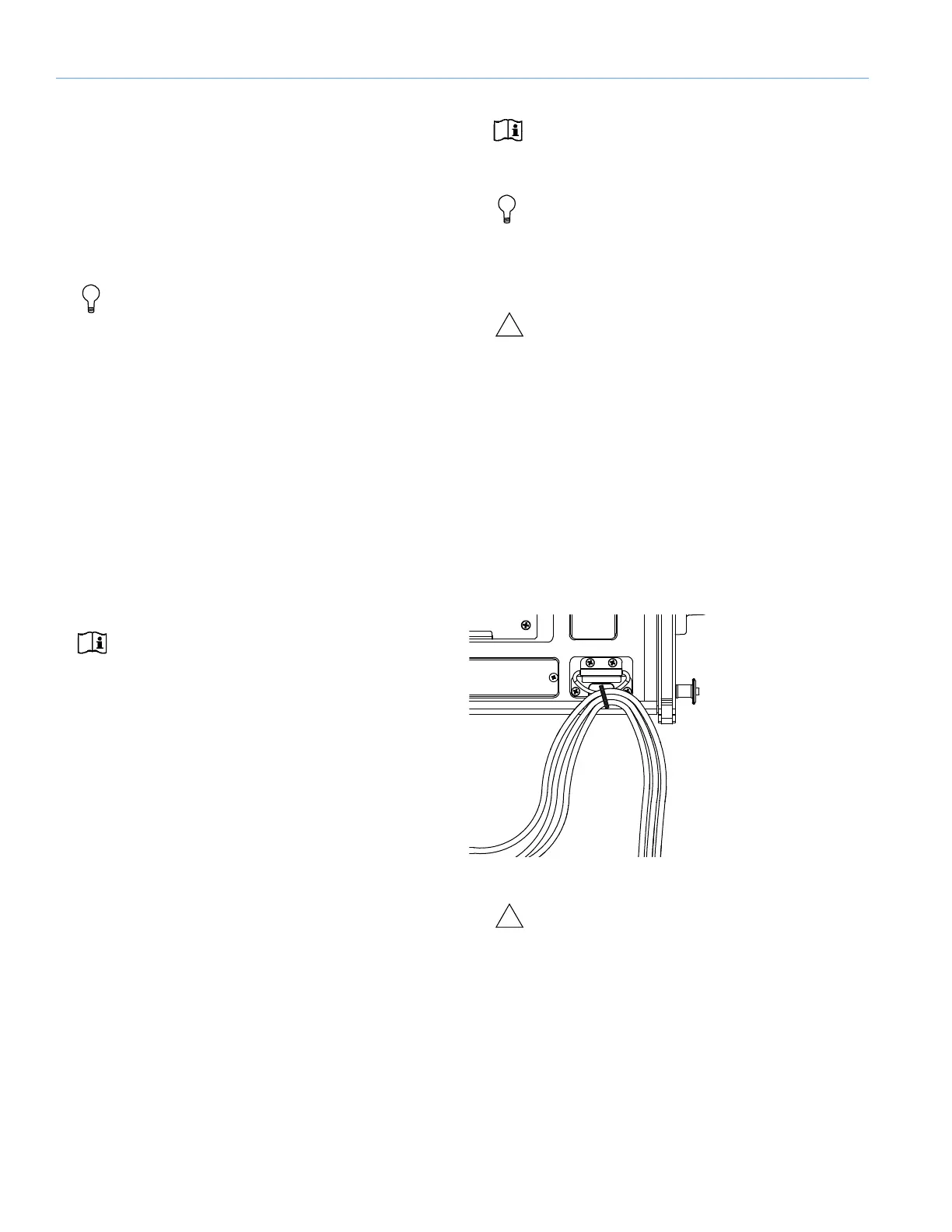
CABLE RINGS
Two cable rings are provided on the rear of the LYON cabinet
(Figure 12). Power and audio cables should be tied off to the
rings to reduce strain on the cables and prevent damage to
them during installation. The cable rings should not be used
for any other purpose.
CAUTION: LYON cable rings should only be
used to reduce strain on cables. The cable
rings should not be used for any other purpose.
TRUPOWER LIMITING
LYON employs Meyer Sound’s advanced TruPower
®
limiting.
Conventional limiters assume a constant loudspeaker
impedance and set the limiting threshold by measuring
voltage alone. This method is inaccurate because
loudspeaker impedances change as frequency content in the
Figure 12: Cables Tied Off to Cable Ring

 Loading...