Operating Instructions
Meyer Sound Laboratories, Inc.
2832 San Pablo Avenue
Berkeley, CA 94702
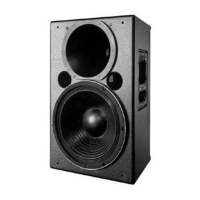
UPA-1C
Loudspeaker
The rigging hardware is so designed that a single point can
support the normal load for the cabinet. In the case of the
UPA-1C the recommended maximum load is 420 lbs
(190 kg) (for example, the weight of the cabinet itself plus
an MSL-3A and a UPA-1C hung beneath). Any of the
individual rigging points is capable of supporting this load
with an adequate safety margin. However, Meyer Sound
strongly recommends that safety lines be run to the other
points. If the structural integrity of any cabinet has been
compromised by damage or negligence, then the safety of
the rigging cannot be assured. All rigging should be done
by competent professionals.
Rigging The UPA-1C loudspeaker has four steel rigging brackets
internally mounted as an integral part of the cabinet design
and the cabinet is supplied with either aircraft pan fittings
(ring and stud),
3
/8" -16 or M10 nut plates, according to user
preference. A flat plate is supplied when no rigging
hardware is specified. All plates are held in place by six
Phillips-head machine screws and can be interchanged at
any time. The handles on the UPA-1C cabinet are provided
solely for moving and carrying the loudspeaker and are not
to be used for rigging purposes.
■ Keep the rear corners of adjacent loudspeakers together
or close to one another.
■ For wider horizontal coverage, spread the angle
between adjacent loudspeakers (to a maximum 45
degrees), by moving the front corners apart. For even
frequency response with two UPA-1C, the minimum
separation angle between cabinets should be 15
degrees.
The high frequency horn of the UPA-1C adds very well in
the horizontal axis, and the apparent sources of both high
and low frequencies in the UPA-1C are co-planar in terms
of propagation. For these reasons, multiple loudspeakers
may be built into an array which behaves acoustically as a
section of a radiating spherical surface. Such arrays offer
precisely controlled coverage and propagate coherent
wavefronts, acting as a close approximation to a point
source. These are the basic rules for forming arrays with
the UPA-1C.
The UPA-1C loudspeaker contains, mounted in the
enclosure, a DC protection and response correction
network for the high-frequency horn driver. The network is
mounted directly behind the MS-12 low-frequency cone
driver on the inside rear face of the cabinet, and is wired in
series with the horn driver.
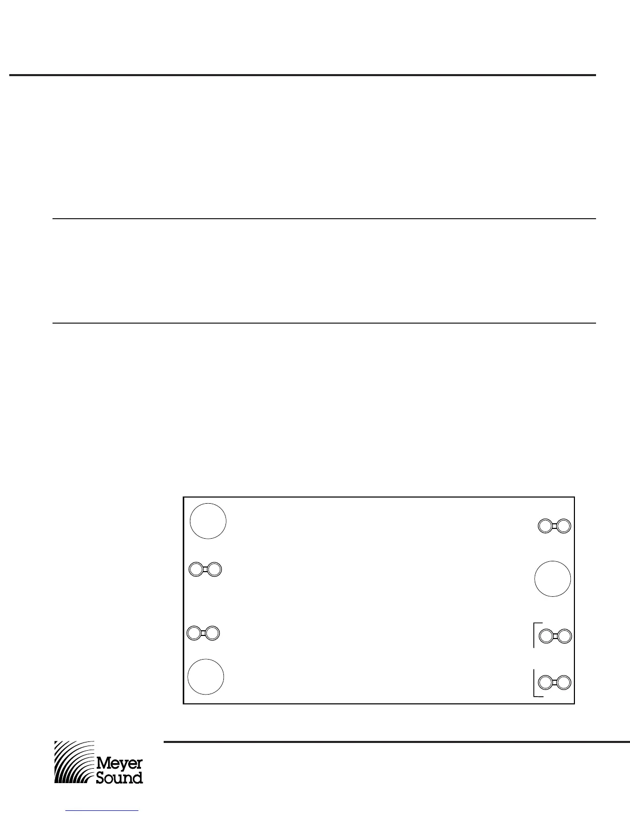
The circuit board is fitted with five terminals, two of which
(labeled AMP- and AMP+) are wired to the Cannon EP-4
connector pins 3 and 4. The other terminals (labeled FLAT
and 16KPK), provide two options for tailoring the system’s
response. With the high driver common (green) wire
connected to the FLAT terminal, the UPA-1C high-
frequency response is nominally flat to 20 kHz. When the
common wire is connected to the 16KPK terminal, the UPA-
1C exhibits a peaked response in the 16 kHz region. This
response may be useful for overcoming propagation losses
when far-field response is a dominant concern.
The UPA -1C is shipped with the high driver common
connected for flat response. Should you desire more high-
frequency energy, simply remove the six bolts holding the
MS-12 in place, pull the MS-12 up and out of the cabinet,
and move the green wire from the FLAT terminal to the
16KPK terminal. Be careful not to disturb the other wires to
the network board or EP connector. When replacing the
MS-12, be certain to tighten the six bolts evenly.
High Frequency
Network
AMP+
WHT
AMP -
GRN
TESTED:_________
DATE:___________
DRVR+
WHT
FLAT
DRVR-
GRN
©1992 Meyer Sound Y-1PD PCB
Assy. # 24.052.103._________Rev_________
16KPK
UPA-1C High Frequency Network Circuit Board
Placement and
Arraying
 Loading...