EasyManua.ls Logo

MFJ Enterprises MFJ-948 User Manual

MFJ Enterprises MFJ-948
10 pages
To Next Page IconTo Next Page
Page #1 background imageLoading...
Page #1 background image
MFJ-948 Versa Tuner II
1
MFJ-948 Versa Tuner II
Instruction Manual
General Information
The MFJ-948 is a 300 watt RF output power antenna tuner that will match any transmitter
or transceiver to virtually any antenna. Peak or average forward and reflected power and
SWR can be read on the illuminated cross-needle meter.
The MFJ-948 uses a "T" matching network and covers all bands between 160 and 10
meters. This network will tune dipoles, inverted-vees, verticals, mobile whips, beams,
random wires, and many other antennas. The MFJ-948 has rear panel connectors for
coaxial, single wire or two wire feedlines. A built-in 4:1 balun allows the use of balanced
open wire, twinlead, or twin-axial feedlines.
An internal eight position antenna-selector switch selects an external 50 ohm dummy load,
two separate coaxial line outputs, or a single wire line-balanced line output. All of these
functions can be selected in tuned (with tuner's "T" network in line) or bypassed (no tuning
circuit) configurations.
Peak Reading SWR/Wattmeter
The illuminated cross-needle meter measures the peak or average FORWARD power,
REFLECTED power, and SWR. The wattmeter is active in all the ANTENNA
SELECTOR positions. To use the wattmeter without the tuning circuit select one of the
ANTENNA SELECTOR positions under BYPASS.
The meter's full scale forward and reflected power range is controlled by the left METER
switch that selects 300W or 30W. If your transmitter runs more than 30 watts of output
power, set this switch to 300W (in position). If your transmitter has less than 30 watts of
output, set this switch to the 30W switch position (out).
Peak envelope power (PEP) is measured when the PEAK or AVERAGE METER push
button (right-hand side) in placed in the PEAK (in) position. Peak power and average
power values are equal with steady unmodulated carriers, FSK, or FM. The PEP power is
twice the average power with SSB two tone test modulation, and may be any amount larger
than the average power with SSB voice signals.
Forward power is displayed on the left-hand FORWARD meter scale. This scale is
calibrated from 0 to 300 watts and is read directly in the 300 watt position. Each picket
(scale mark) represents 25 watts between 300 and 100 watts, 10 watts between 100 and 10
watts, and has a single 5 watt picket below 10.
Downloaded from www.g7syw.com
www.g7syw.com
Question and Answer IconNeed help?

Do you have a question about the MFJ Enterprises MFJ-948 and is the answer not in the manual?

MFJ Enterprises MFJ-948 Specifications

General IconGeneral
TypeAntenna Tuner
Frequency Range1.8-30 MHz
Impedance50 Ohms
Tuning MethodManual
Antenna SwitchYes
Power Rating300 W PEP
MeterBuilt-in SWR/Wattmeter
Power Handling300 W PEP, 150 W continuous

Summary

General Information

Peak Reading SWR/Wattmeter

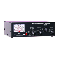
Describes the cross-needle meter for forward/reflected power and SWR measurements.

Antenna Selector

Interconnections

Installation

RF Voltage Safety Warning

Warns about high RF voltages on rear terminals and the risk of burns or damage.

Connecting System Components

Provides instructions for connecting the transmitter, coaxial feedlines, and wire antennas.

Using The MFJ-948

"T" Network Operation Details

Explains the function of the "T" network, capacitance, and inductance controls.

Transmitter Tuning & Bypass

Covers tuning the transmitter output and using the bypass function.

Adjustment Procedure

Tuning Chart and Initial Setup

Presents the tuning chart and initial steps for setting controls by frequency.

Fine-tuning Controls

Details how to adjust TRANSMITTER and ANTENNA MATCHING for lowest SWR.

Power Adjustment After Tuning

Guidance on increasing transmitter power once low SWR is achieved.

Troubleshooting and Difficulties

Arcing Issues

Advice for troubleshooting tuner arcing at rated power levels.

General Tuning Difficulties

General advice for when the tuner fails to tune or operates improperly.

Grounding and Antenna Hints

Grounding Best Practices

Explains the importance and methods for effective RF and lightning grounding.

Antenna Placement and Configuration

Recommendations for antenna location and specific configurations for optimal performance.

Operator Safety Grounding

Emphasizes connecting a good earth ground for operator safety.

Matching Problems and Solutions

Feedline Length Impact

Explains how feedline and antenna lengths can cause matching difficulties.

Improving Antenna Matching

Offers suggestions to reduce complexity when matching antennas.

Technical Assistance

Schematic