MFJ-1798 Vertical Antenna Instructions
6
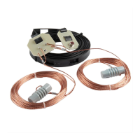
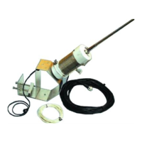
[ ] One balun and feedline assembly with small coil and capacitor
network
Group B (Hardware Bag #1)
[ ] One bag of hardware containing the following parts groups:
(1) Five #4 self tapping screws (4) Twenty-nine 6-32 nuts
Five 4-40 x 3/8" screws Two 10-32 split ring washers
Five 1/4-20 x 1-3/4" bolts
Four #4 flatwashers
Five 1/4" split ring washers
(2) Thirty 6-32 x 1/4" screws (5) Six 3/16" ID aluminum couplers
Twelve 10-32 nuts Six black cable ties
Two white nylon insulators
(3) Twenty-seven 6-32 x 5/8'' screws One red plastic cap
Two 10-32 x 1-3/4" screws
Five 1/4-20 nuts
Group C (Hardware Bag #2)
[ ] One bag of large hardware containing the following parts groups:
(1)Three small aluminum "L" brackets (3) Four counterpoise clamps with no flange
Three triangular aluminum brackets Four counterpoise clamps drilled flange
One rectangular aluminum bracket One 20 meter adjustment "U" clamp
(2)Five flat rectangular fiberglass stub insulators
One set of fiberglass and aluminum
counterpoise support assembly plates
One hollow center, square aluminum plate
Group D (Hardware Bag #4)
[ ] One bag containing the following:
Seven hose clamps (4 clamps are pre-installed on the angle
bracket in this bag.
3 clamps are packed loose in the bag to be sed in
step 9, 10,
and 11 on page 11.)
Two "U" bolts with saddle brackets, nuts, and split wahers to fit
masts under 1-1/2" OD
35" (approximately) of small tinned wire