MFJ-259 Instruction Manual HF/VHF SWR Analyzer
14
C(pF) =
1
00003948F L
F = MHz L = H
2
.
µ
Measure inductance
1.
Connect an unknown inductor with the highest value standard capacitor in series.
2.
Connect the series LC circuit to "ANTENNA" connector with a 50
Ω
resistor in series.
3.
Adjust the tune knob through the bands until you get the lowest SWR. If you do not get a
deep meter deflection change to the next smaller value standard capacitor and try again.
Repeat the process until you get low SWR.
4.
Solve this equation using F as the resonant frequency and C as the capacitance of the
standard capacitor.
L( H) =
1
00003948F C
F = MHz C = pF
2
µ
.
RESONANT FREQUENCY OF TUNED CIRCUITS
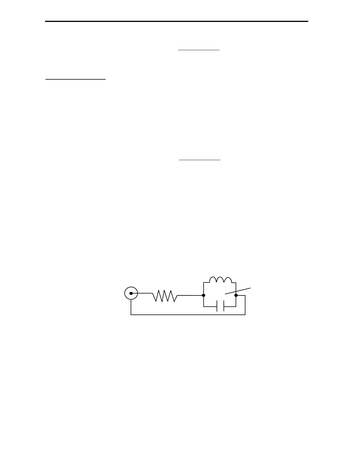
The MFJ-259 can be used to measure the resonant frequency of tuned circuits by two
methods. The first method involves placing a 50 ohm resistor in series with the MFJ-259
"ANTENNA" connector. The MFJ-259 connects through the resistor to the parallel tuned
circuit. This circuit is for high capacitance values.
Tune the MFJ-259's frequency until the "SWR" meter reaches the highest SWR. This is the
resonant frequency of the load.
"ANTENNA"
To the MFJ-259's
connector
All leads should be short
50 ohms
Hi - "C