MFJ-259C Instruction Manual HF/VHF SWR Analyzer
2
1.0 Introduction
The MFJ-259C is a compact battery-powered RF-impedance analyzer that covers 0.53-230
MHz in nine overlapping bands. Fully portable and self contained, it delivers a wide range of
basic and advanced RF measurements to present a complete picture of your antenna systems
and networks. It also measures capacitance, inductance, and serves as a discrete signal
generator and frequency counter for the test bench. The MFJ-259C is the latest entry in a long
line of time-tested designs using proven technology and rugged construction to ensure years
of reliable service. Please read through this manual carefully before powering up your analyzer
for the first time. The manual contains important safety information you'll need to know to avoid
damaging your unit. There's also valuable operating instruction to help you to take advantage
of its full range of functions and features right away.
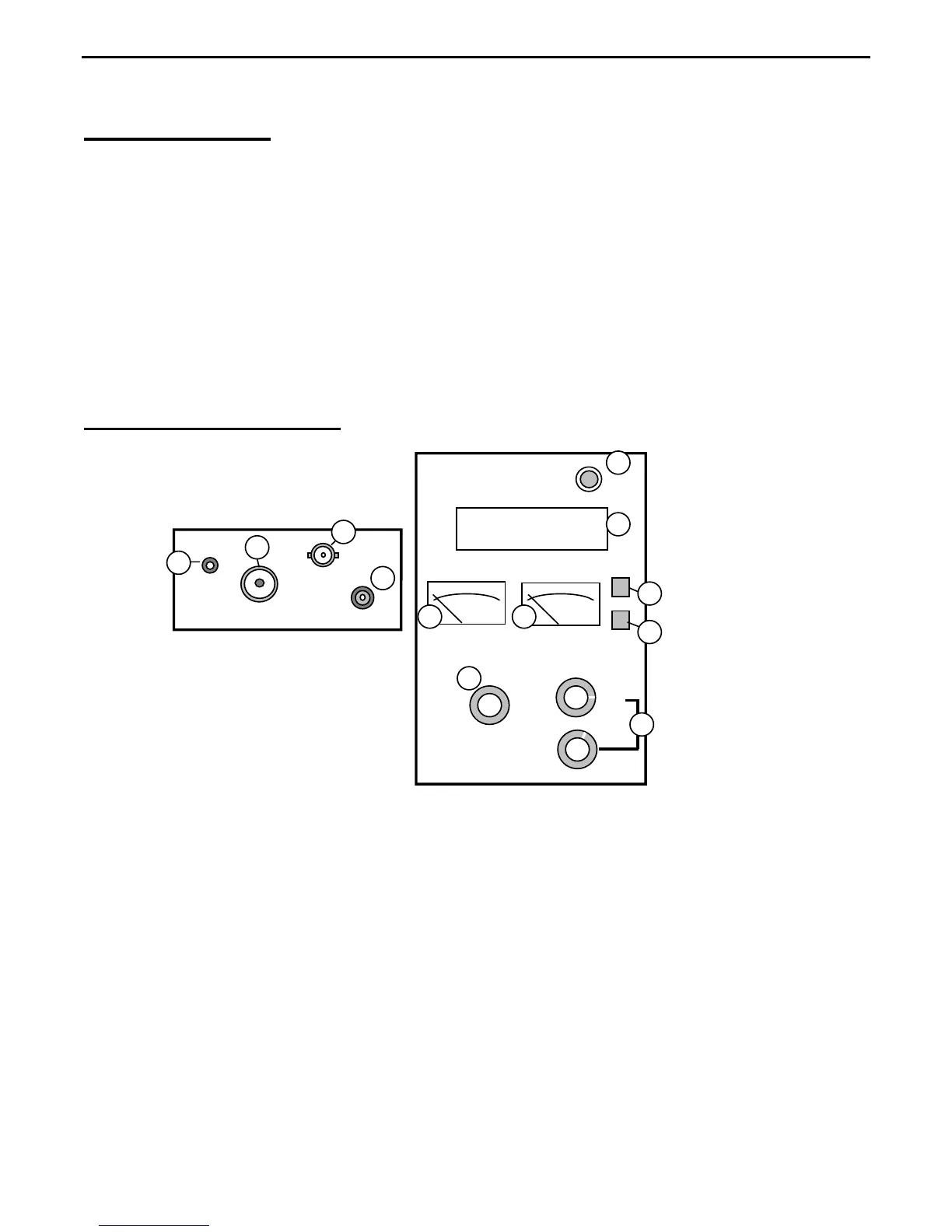
1.1 MFJ-259C Control Layout
155-230
113-155
67-113 28-67
11-28
4.7-11
2.1-4.7 1.0-2.1
0.53-1.0
Lower
Range
TUNE
FREQUENCY MHz
POWER
GATE
MODE
SWR
IMPEDANCE
MFJ HF/VHF SWR ANALYZER
MODEL MFJ-259C
ANTENNA
GROUND
FREQUENCY
COUNTER
INPUT
POWER
13.8 VDC
MFJ
POST
1
2
3
4
5
6
78
9
10
11
12
1. Antenna Port: SO-239 for attaching antennas and RF devices under test.
2. Ground Post: Binding post for attaching leads to chassis ground.
3. Counter Input: BNC-female input jack for analyzer's Frequency Counter function.
4. External Power: 2.1-mm power jack accepts power adapter or supply (13.8V + center pin).
5. Power Switch: Applies power from internal batteries or external power source.
6. LCD Display: Two-line digital display presents operating frequency and measured data.
7. SWR Meter: Provides continuous analog readout of SWR measurements (Zo=50).
8. Impedance Meter: Displays impedance magnitude or reactance measurements.
9. Gate: Push button sets counter gate speed, performs other specified functions.
10. Mode: Push button selects measurement mode, performs other specified functions.
11. Tune: VFO capacitor, provides analog frequency control for the analyzer's generator.
12. Frequency: High and low-range band switches select analyzer's operating range.