MFJ-259C Instruction Manual HF/VHF SWR Analyzer
3
1.2 Analyzer Measurement Functions
• SWR: LCD display and analog meter, Zo = 50Ω or Zo programmable
• Complex Impedance: Resistive and Reactive components (R ±jX)
• Vector Impedance: Z-magnitude plus Phase Angle
• Impedance (Z): Analog meter display, Zo=50 Ω
• Return Loss: Digital display, in dB
• Inductance (uH), Reactance (XL): Digital display with frequency
• Capacitance (pF), Reactance (Xc): Digital display with frequency
• Resonance: Digital and analog reactance null (X=0) with frequency
• Electrical Length: Digital, measured in feet.
• Feedline Loss: Digital, measured in dB
• Signal Frequency: Discrete counter function with three gate speeds
• Signal Generation: 20-mW (3-Vpp) output into 50 Ω, > -25 dBc suppression.
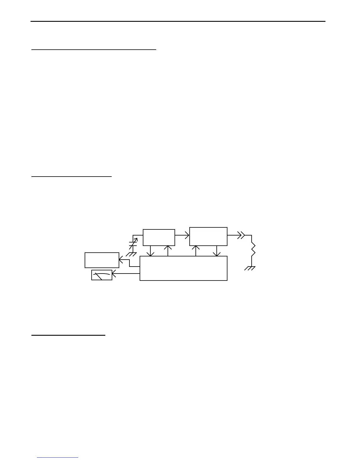
1.3 Theory of Operation: The MFJ-259C has four basic electronic elements. (1.) A tunable
VFO with counter readout that generates RF signals to energize the load or device under test
(DUT). (2.) A Directional Coupler (or bridge) to measure RF incident and reflected voltages
sent to the load. (3.) A Central Processor that reads bridge voltages and processes them into
usable data. (4.) A LCD Display and two analog meters that present all computed data visually.
The processor also performs other mathematical calculations and conversions.
A/D Converter and Processor
VFO
Bridge
Display
Tune
Load
(DUT)
Ant Jack
LCD
Meters
The MFJ-259C will serve as your eyes and ears when working with RF systems. However, all
handheld analyzers share certain limitations, and being aware of them will help you to achieve
more meaningful results.
1.4 Local Interference: Like most hand-held designs, the MFJ-259C uses a broadband
directional coupler that is open to incoming signals across the radio spectrum. Most of the
time, the unit's built in +5-dBm RF generator is powerful enough to override any interference
caused by stray pickup. However, under some circumstances, a powerful nearby transmitter
could inject enough RF energy through the antenna being tested to overload the coupler and
disrupt readings. If overload occurs, measurements may become erratic or SWR readings
inaccurately high. These occurrences are rare, but if it becomes a problem at your particular
testing location, the MFJ-731 Tunable Analyzer Filter is especially designed to notch out
unwanted signals with minimal impact on analyzer accuracy.