MFJ-259C Instruction Manual HF/VHF SWR Analyzer
25
voltage at the input port generated by the MFJ-259C to the load voltages at the other ports
using standard power-level conversions.
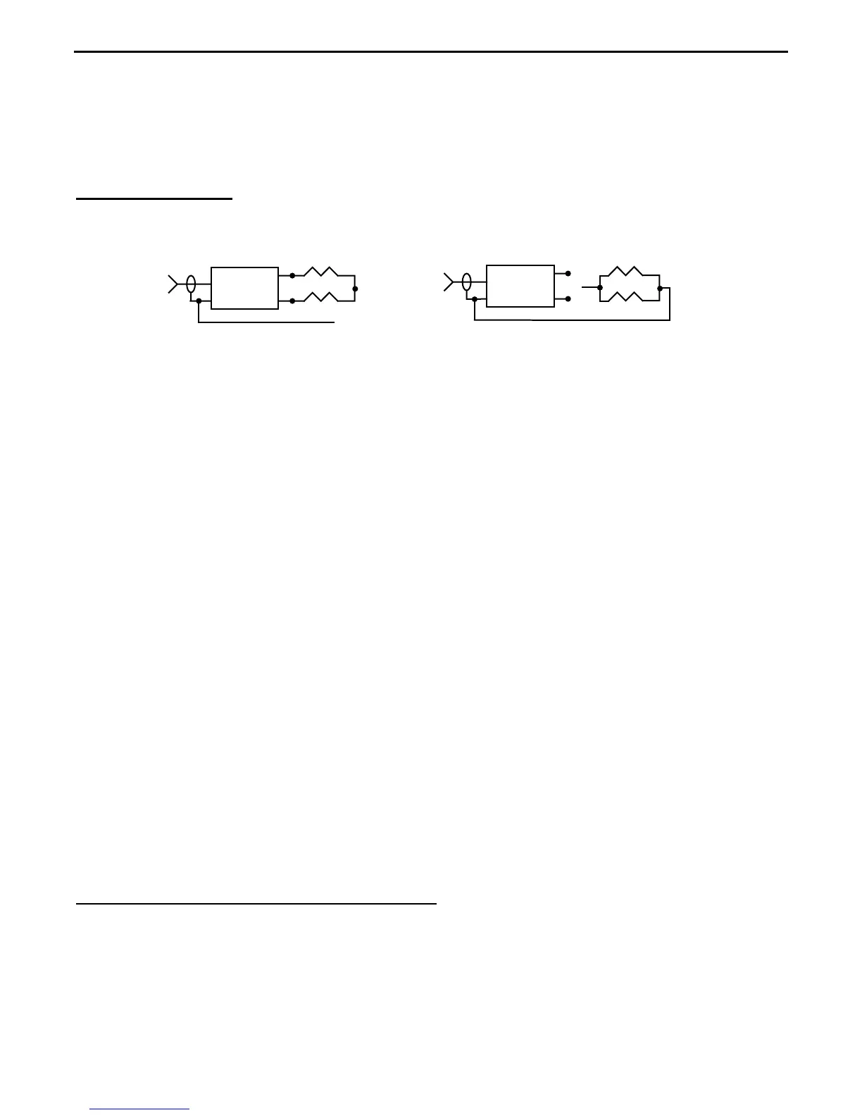
7.7 Testing Baluns
: To evaluate the performance of "current" and "voltage" style baluns,
follow the outlined procedures referring to Figures A and B below:
Balun
>
A
C
B
Clip Lead
50 Ohms
Unbal
R1
R2
Balun
Clip Lead
50 Ohms
Unbal
R1
R2
<
A
C
Fig A
Fig B
[ ] Set the analyzer to the default
R&X function in the Basic menu.
[ ] Set the
VFO to the midpoint of the Balun's operating range
[ ] Connect the analyzer to the balun's 50-ohm unbalanced input.
[ ] Terminate the balanced side with equal-value load resistors as shown:
Use two equal-value non-inductive resistances. For a 4:1 balun with a 200-ohm secondary,
configure a pair of 100-ohm resistors in series. For a 1:1 balun with a 50-Ohm secondary,
connect 50-Ohm resistors in parallel to make a pair of 25-Ohm resistors, or if using standard
values, connect 47 and 56-Ohm resistors in parallel to make up 25.5 Ohm loads. To evaluate
your balun, refer to
Figure-A:
[ ] Measure
SWR while connecting the grounded clip lead to points A, B, and C.
Current Balun: A well-designed current balun will exhibit low SWR over its entire operating
range with the clip lead installed at
A, B, or C.
Voltage Balun: A well designed voltage balun will exhibit low SWR over its operating range
with the clip lead installed at
position B. However, it will show poor SWR with the clip lead
installed at
A or C (elevated readings should be the same). To further test the voltage balun,
connect as shown in
Figure-B. If operating properly, SWR will be remain low with the resistors
connected from either output terminal to ground.
A well-designed current balun works best for maintaining current balance on a dipole under
"real world" conditions where some asymmetry in loading may exist between the two legs. The
current balun also has the highest power capability and lowest loss for given materials.
7.8 Analyzing RF chokes for Self-resonance: Large RF chokes often have frequencies
where the distributed capacitance and inductance form a low impedance
series-resonance.
Series resonance occurs because the choke winding acts like a succession of back-to-back L-
networks. This condition can lead to three problems:
• End-to-end Impedance of the choke becomes very low.