MFJ-902B Instruction Manual
3
INTRODUCTION
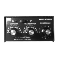
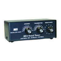
The MFJ-902B Travel Antenna Tuner was specially compact-built for Icom IC-
706MKIIG, Yaesu FT-100, Kenwood TS-50, and other rigs with a built-in SWR
Meter.
You can operate 80 through 6 Meters -- anywhere with any transceiver. It’s
great for mobile, base, backpack, etc. The MFJ-902B handles 150 watts RF
output and has a tuner bypass switch.
INSTALLATION
The MFJ-902B should be installed between the transmitter and antenna.
1. Locate the tuner in a convenient location at the operating position.
2. Use a 50 ohm coaxial cable to connect the transmitter or transceiver to the
SO-239 labeled TRANSMITTER on the back of the tuner.
3. Connect an antenna feed to the appropriate tuner output:
a.) COAX-FEED to the SO-239 connector labeled ANTENNA.
b.) RANDOM WIRE
MFJ-902: A random wire may be used by connecting to the center of
the SO-239 connector with the supplied plug.
The MFJ-902B must be grounded when using a random wire.
4. Connect your tuner and transmitter to a good earth ground.
OPERATION
This tuner has a BYPASS/TUNE switch located on the back of the unit. Simply
place the switch toward the BYPASS labeling to completely bypass the tuning
circuit. Change the switch toward the TUNE labeling to place the tuning circuit
between the transmitter/transceiver and the antenna.
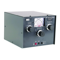
This tuner also has a 6M/HF switch located on the front of the unit that changes
the tuner into a “L network” for 6 meters. This will allow the tuner to match
loads in the 50 Mhz range. This setting can also be used to match some
antennas on the higher HF bands allowing the tuner to be slightly more efficient.
In this tuner the TRANSMITTER and ANTENNA matching controls have
maximum capacitance at position 0 (fully meshed), and minimum capacitance at