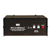
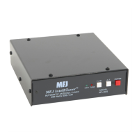
The MFJ-9234 Mini Loop Tuner is a compact, high-efficiency device designed to transform any wire loop into a multi-band transmitting antenna system. It is specifically engineered for QRP (low power) operation, handling up to 25 Watts across all modes, and is optimized for 50-ohm impedance. Its small physical profile (1.5" D, 2.75" W, 4.0" H) makes it ideal for portable and on-the-go use, often mounting directly to a radio.
Function Description:
The core function of the MFJ-9234 is to resonate various lengths of wire, creating a high-Q (quality factor) tuned circuit that acts as a transmitting loop antenna. It achieves this by utilizing special low-loss capacitors, ensuring high efficiency in the antenna system. The tuner interfaces this high-Q transmitting loop circuit with any length of 50-Ohm coaxial cable from the radio. A key advantage of this system is that it does not require a ground, radials, or a counterpoise system, simplifying setup. It can be used with wire loops of any shape, such as circles, squares, or rectangles. For optimal efficiency, the manual recommends using wires that approximate one-quarter wavelength and are erected in a circular shape. The tuner is a passive network, meaning it does not require an external power supply.
Important Technical Specifications:
- Maximum Input Power: 25 Watts (all modes).
- Physical Profile: 1.5" D x 2.75" W x 4.0" H.
- Frequency Coverage: The tuner uses fixed wire lengths to cover roughly a 1.5:1 frequency ratio (e.g., 28-18 MHz, 10-7 MHz). Exact frequency coverage is dependent on the specific installation, including wire length, loop diameter, loop shape, height above ground, and other environmental factors.
- Included Accessory: 55 feet of wire for constructing a loop.
- Loop Construction Materials: The loop can be constructed from wire, tubing, sheet, or 1" wide PC board.
- Recommended Loop Lengths:
- Single-Band:
- 80-M: 63.0 ft (19.20 m)
- 40-M: 28.0 ft (8.53 m)
- 30-M: 20.0 ft (6.96 m)
- 20-M: 13.0 ft (3.96 m)
- 17-M: 9.0 ft (2.75 m)
- 15-M: 7.0 ft (2.13 m)
- 12-M: 5.5 ft (1.68 m)
- 10-M: 4.0 ft (1.22 m)
- Multi-Band:
- 40/30-M: 20.0 ft (6.96 m)
- 30/20-M: 13.0 ft (3.96 m)
- 30/20/17-M: 9.0 ft (2.75 m)
- 20/15-M: 7.0 ft (2.13 m)
- 17/15/10-M: 4.0 ft (1.22 m)
- RF Voltage Potential: The high-Q resonant loop circuit can produce dangerous RF-voltage potentials, even at low QRP power levels, capable of causing painful RF burns.
- Ground Losses: For 14 MHz and higher bands, ground losses are minimal near ground. For 7 MHz and lower bands, ground losses become significant on the ground floor; operation on a second or third floor is recommended to reduce these losses.
- Mounting Orientation: For minimum ground loss near ground, the loop should be mounted vertically. For higher elevations (relative to wavelength), horizontal mounting also yields low ground losses.
Usage Features:
- Ease of Setup: The system is designed for quick setup, making it suitable for apartments, motel/hotel rooms, or portable operations where antenna restrictions exist.
- Low Radiation Angle: The radiation pattern of the loop antenna rivals that of full-size dipoles.
- Quiet Reception: Loop antennas are known for extremely quiet reception, with the high-Q circuit rejecting overload from out-of-band interference and transmit harmonics.
- Experimental Design: The tuner encourages experimentation with loop antenna designs, allowing users to optimize parameters for their specific operational configuration. Freeware modeling programs are suggested for this purpose.
- Tuning Process:
- Initial Placement: Position the MFJ-9234 Mini Loop Tuner at the chosen operating location, typically connected directly to the back of the radio. Connect the loop antenna to the binding posts on the front panel.
- Loop Formation: Use the provided wire and non-conductive fasteners (e.g., plastic clothespins) to form a loop that encloses as much area as possible. A circular shape encloses the maximum area.
- Preliminary Settings: Set the TUNING control to "Low Freq" and the MATCHING control to "Min C".
- "Ear-ball" Tuning: Tune the transceiver/receiver to the desired band and frequency. Adjust the TUNING and MATCHING controls for maximum noise and S-Meter reading. This "ear-balling" process helps find a peak in reception before transmitting.
- Fine Tuning (with power): Apply 5-10 Watts of power. Adjust TUNING and MATCHING controls for minimum SWR on an external SWR/Wattmeter. Continue adjusting until no further improvement in SWR is observed. If needed, power can be increased up to 25 Watts for communication.
- Frequency Changes: For frequency changes greater than 5 KHz, re-adjustment of the TUNING controls for minimum SWR will likely be necessary. TUNING clockwise increases frequency, counter-clockwise decreases it. Larger frequency excursions may also require MATCHING control adjustment.
Maintenance Features:
- RF Hazard Precautions:
- Acute Injury Warning: DO NOT touch or make skin contact with the Loop Connectors or Loop Antenna Wire while transmitting. High RF voltages can cause severe RF burns.
- Power Limitation: Do not exceed the recommended power limitation of 25 Watts.
- Arcing Detection: If arcing is detected, immediately stop transmitting. Check connections and proximity to objects that might be causing the arcing. If arcing appears to be inside the tuner, reduce output power and re-check.
- FCC Compliance: Users must adhere to all PRECAUTIONS, WARNINGS, and FCC Guidelines for Human Exposure to Radio frequency (RF) Electromagnetic Fields, specifically FCC OET Bulletin 65, Supplement B. This includes maintaining safe operating distances from the loop antenna to ensure compliance with Maximum Permissible Exposure (MPE) limits for both controlled and general populations.
- Technical Assistance: For problems not resolved by the manual, users can contact MFJ Technical Service via phone (662-323-0549 or 662-323-5869), FAX (662-323-6551), or email (techinfo@mfjenterprises.com). When seeking assistance, it is recommended to have the unit, manual, and station information readily available.
- Warranty: The product comes with a Limited 12 Month Warranty, covering defects in material and workmanship from the date of purchase, provided the dated proof-of-purchase is retained. The warranty covers repair or replacement at MFJ's option, with a $7.00 fee for postage and handling. The warranty is not voided by attempts to repair defective units, and technical consultation is available. Out-of-warranty service is also available, with repair charges and COD shipping.