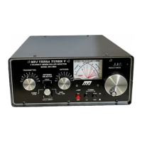
MFJ-925 Super-Compact IntelliTuner Automatic Antenna Tuner Instruction Manual
© 2006 MFJ Enterprises, Inc.
7
Jumper JP2, located behind the front panel circuit board, selects the radio to be connected to the
Radio Interface connector. Set this jumper to the “I” position to interface with radios that are
compatible with the Alinco EDX-2 tuner, Icom AH-3 and AH-4 tuners. Set the jumper to the “K”
position to interface with radios that are compatible with Kenwood AT-300 tuner. Set the jumper to
the “Y” position to interface with Yaesu FT-100; “1” position to interface with Yaesu FT-817, FT-
857 or FT-897; and “2” position to interface with Yaesu FT-847. If no cable is connected to the
Radio Interface connector, set the jumper to the “0” position to disable the interface. Default is “0”.
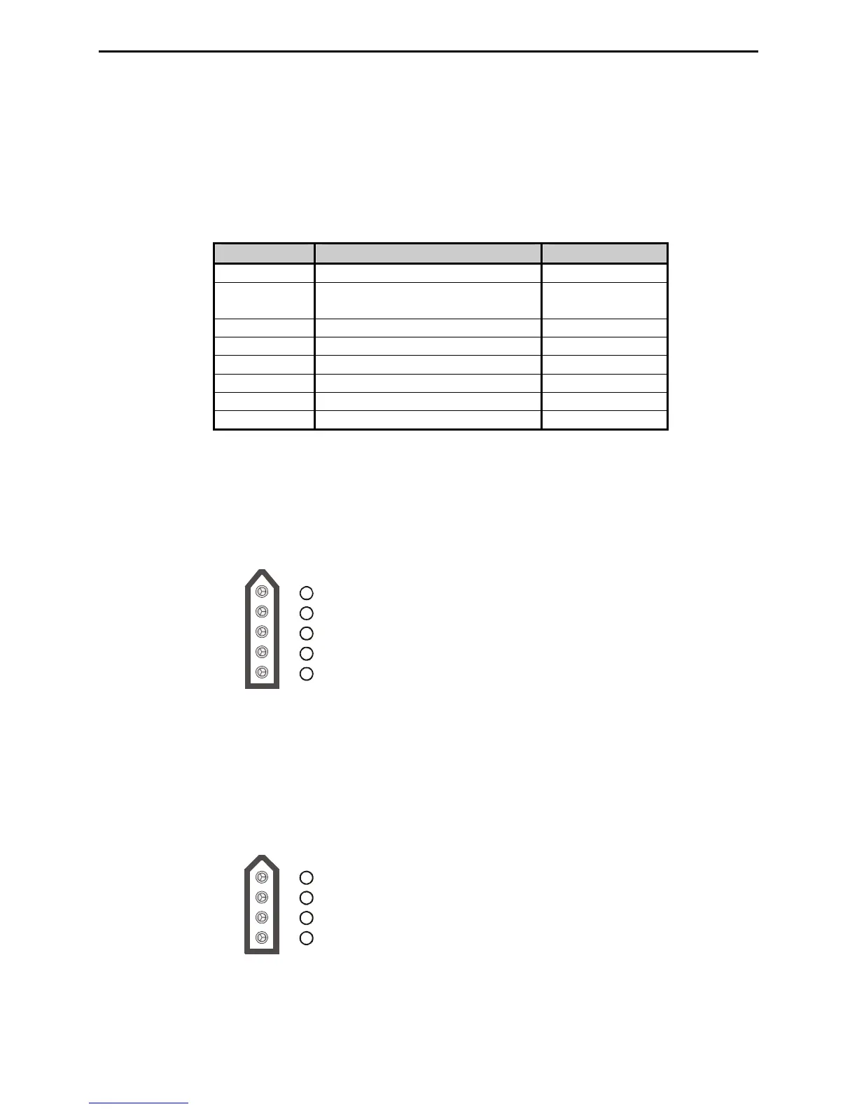
Jumper JP2 To Interface Using
0
No Radio Interface --
I
Alinco
Icom
MFJ-5114A
MFJ-5114I
K
Kenwood MFJ-5114K
Y
Yaesu CAT (FT-100) MFJ-5114Y
1
Yaesu CAT (FT-817/857/897) MFJ-5114Y
2
Yaesu CAT (FT-847) MFJ-5114Y2
3
Reserved --
4
Reserved --
Table 1. Jumper JP2 Setting.
The MFJ-5114A interface cable provides power and control between an Alinco radio and the MFJ
automatic tuner. Supported Alinco radios are DX-70, DX-77, and any Alinco radio that supports the
Alinco EDX-2 tuner.
Pin 1 (Ground) connects to pins 4 and 5 of Radio Interface Plug.
Pin 2 (+13.8V) connects to pins 2 and 3 of Radio Interface Plug.
Pin 3 (Key) connects to pin 6 of Radio Interface Plug.
Pin 4 is not connected.
Pin 5 (Start) connects to pin 8 of Radio Interface Plug.
5
1
2
3
4
Figure 6. Alinco Interface Cable.
The MFJ-5114I interface cable provides power and control between an Icom radio and the MFJ
automatic tuner. Supported Icom radios are IC-706, IC-707, IC-718, IC-725, IC-728, IC-736, IC-738,
IC-746, IC-756, IC-765, IC-775, and any Icom radio that supports the Icom AH-3 or AH-4 tuner.
Push and hold the radio’s [TUNER] button for two seconds to start the tuning process. Push
[TUNER] quickly to bypass the tuner.
Pin (Key) connects to pin 6 of Radio Interface Plu
Pin (Start) connects to pin 8 of Radio Interface Plug.
Pin (Ground) connects to pins 4 and of Radio Interface Plug.
2
Pin 3 (+13.8V) connects to pins 2 and 3 of Radio Interface Plug.
45
1g.
1
2
3
4
Figure 7. Icom Interface Cable.