Do you have a question about the MG TR-EVO and is the answer not in the manual?
Essential to comply with manual instructions to prevent damage.
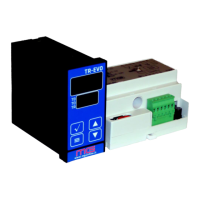
Details on dimensions, weight, mounting, material, protection, display, and power.
Details on dimensions, weight, mounting, material, protection, and power.
Technical data for DIN rail adapter, including dimensions and material.
Explains temperature adjustment via resistance variation without external sensors.
Describes autonomous operation via display/keypad or connection to PLC/PC.
Instructions for qualified staff, checking power supply and ground.
Reserve space in electrical cabinet for DIN rail mounting.
Panel cutout and mounting instructions for the display module.
Advice on transformer positioning and cable length optimization.
Detailed explanation of wiring terminals on the power unit.
Supported heating element alloy types and names.
Formulas for calculating power (Pr), resistance (R), secondary voltage (Vs), and power (Pt).
How to configure switches based on calculated current.
Procedure to acquire heating element cold resistance for proper operation.
Describes the device's standby state and how heating starts.
Explanation of the LEDs indicating heating start, working temp, and conclusion.
'Rapid temperature change' error and solution.
'Insufficient voltage reading' error and causes.
'Insufficient current reading' error and causes.
'Too high voltage reading' error and causes.
'Too high current reading' error and causes.
'Voltage not reaching the heating element' error and causes.
'Current not passing through the heating element' error and causes.
'Voltage reaching the heating element not read' error and causes.
Configuration via EIA/TIA485 interface with PLC or PC.
Configuration directly using the device's keypad and display.
Explanation of how to set and save basic parameters like pre-heating temperature.
Sets the maximum pre-heating temperature limit.
Sets the maximum heating temperature limit.
Selects the operating mode for temperature control.
Selects the unit for timer measurements (hundredths or tenths of a second).
Selects the temperature unit (Celsius or Fahrenheit).
Configures analogue input for potentiometer or voltage control.
Specifies the heating element alloy for correct temperature indication.
Adjusts TRIAC firing for performance in specific cases.
Adapts temperature control to specific power usage.
Selects communication format for serial bus.
Module to compile for choosing system components and preparing diagrams.
Options for cooling method (no, air, water).
Selects how sealing timing is managed.
Options for the user interface type.
| Type | Gamepad |
|---|---|
| Frequency | 2.4 GHz |
| Connectivity | Wireless |
| Platform | PC |
| Battery | Lithium battery |
| Compatibility | Windows |