40
75D0004
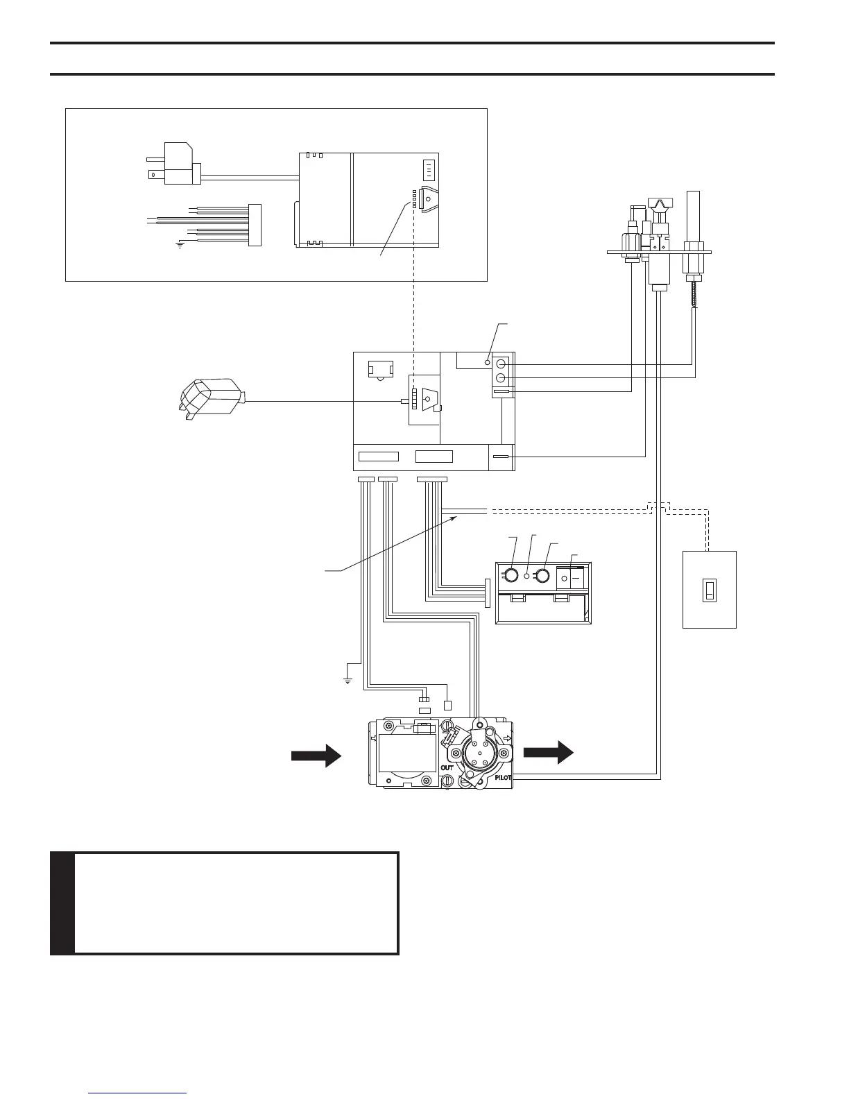
MLDV Series Gas Fireplace
To Junction Box
in Fireplace
Optional
AC Module
{
White
Black
Optional
Light
White
Black
{
Optional
Blower
White
Black
{
Optional
Aux.
Green
Plug in
Connector
Connector Pin
To Control Board
Input 300 Watt Max. Each
Optional A/C Module Replaces 6V Adapter
When Used
6V AC
Adapter
Control Board
RF Receiver
ON/OFF Button
Pilot
Black / Thermopile
Red / Thermopile
Sensor
Ignitor / Sparker
Conversion
NG/LP
Plug-in Connector
Control Board to Command Center
OFF/LO
LED
ON/HI
Master Switch
Command Center
Optional
Wall Switch
Plug-in Connector
Stepper Motor to
Control Board
DC Power/Green
Ground
Plug-in Connector
Control Board to
Solenoid
Gas In
Gas Out
Pilot Gas Tubing
Valve
Figure 58 -
Signature Command Wiring Diagram
Wall switch wires must be con-
nected together if a wall switch is not
being used.
 Loading...