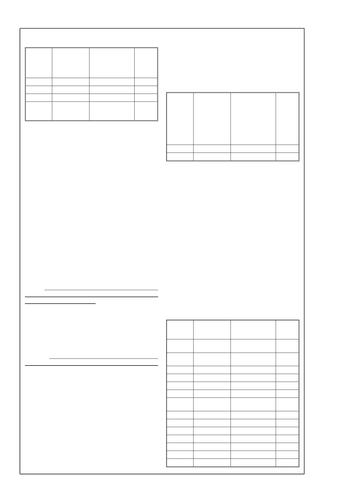
5. Flow
31 Unit flow L/s
m3/s
m3/h
m/s
cfm
32 Max flow 0...32767
33 Scale flw 0...32767
34 Set flow 0...32767
92 Compens OFF
ACTUAL
NORMAL 0
If the unit isn´t to be used for flow measurement,
nothing has to be programmed under the parameter
group “Flow”.
Programme the unit for flow l/s, m
3
/s, m
3
/h, m/s or
cfm (cubic feet / minute).
The basic flow calculation used is made with ÖdP.
To have the display and the output corresponding to
the actual flow or velocity in the selected unit it is
necessary to make some calculations.
Different manufactors of flow measurement devices
have different calculation, but common for all is ÖdP.
Use the actual formula to calculate the max flow for
the factory calibrated measure range. The calcu-
lated flow or velocity at 20 °C is then programmed
under “Max flow” in the selected unit. The flow
range for max. output signal is programmed in
"Scale flw”, e.g. 3,5 m
3
/s = 10 VDC.
In parameter "Scale Flw", the flow should be en-
tered at actual temperature or in normal flow if tem-
perature compensation is activated. The output sig-
nal is linear compared to the flow or velocity.
NOTE ! If the range is not scaled, the same value in
parameter "Max flow" must also be programmed
into parameter "Scale flw". When scaling the flow,
note that the accuracy depends on the “Max flow”
range.
If adjustment of the displayed actual flow or velocity
must be done, it is possible to do under “Set flow”.
Programme the actual flow coming from a reference
flow sensor or equal.
NOTE ! The programming must be done at the
same time as the reference values are measured
(PGM-key is pressed).
Automatically the “Max flow” programming will be
changed for the new values. If the unit is connected
to a BMS system or equal, the “Max flow” or if
scaled, the “Scale flw” and the output signal must be
programmed in the connecting system.
With the parameter "Compens", the calculated flow
can automatically be compensated for changes in
the air density due to temperature changes. With
the parameter set to "ACTUAL" the flow is calcu
-
lated by the current temperature. With the parame
-
ter set to "NORMAL 0", the flow will be calculated as
if the temperature was 0 °C.
When the parameter is set to "ACTUAL", the letter
"A" is displayed in front of the selected flow unit, e.g.
Am3/s, and when set to "NORMAL 0", the letter "N"
is displayed in front of the selcted flow unit, e.g.
Nm3/h. This is to indicate that the the flow is calcu
-
lated for the current temperature or in normal flow.
6. Temperature
93 Input OFF
0..10V
2..10V
0..20mA
4..20mA
Pt-100L
Pt-100H
Pt-1000L
Pt-1000H
94 Min Input -30...600
95 Max Input -30...600
Within this parameter group, the temperature sen
-
sor input is selected. It is possible to use an ana
-
logue signal, 0/2...10 VDC or 0/4...20 mA, Pt-100 or
Pt-1000 sensor.
When using an analogue signal the signal must be
scaled in parameter "Min Input" and "Max Input".
Pt-100 and Pt-1000 has two measuring ranges, ei-
ther low (L) or high (H).
The low selection has a temperature range of
-30...80 °C and the high selecting has a tempera-
ture range of 0...600 °C. The setting of parameters
"Min Input" and "Max Input" will automatically be set
for the low or the high range.
Change the setting of the DIL-switch located in the
upper right corner on the temperature input circuit
board, to correspond with the programmed settings,
VDC, mA, Pt-100 or Pt-1000. See figure on the last
page.
7. PI2 controller
35 Source OFF
dP
FLOW
36 Mode AUTO
HAND
37 Output DIRECT
REVERSE
52 Temp 1 -30...600
53 SP1 -32768...32767
54 Temp 2 -30...600
55 SP2 -32768...32767
56 SPC OFF
TEMP
39 NZ [%] 1...50
40 P-band 0...9999
41 I-time [s] 0...999
42 BZ [%] 0...100
43 I-time BZ 0...999
96 Min out 0,00...100,00
97 Max out 0,00...100,00
6
© AB MICATRONE 2009-02-12 [H:\ Apps \ Typeset \ Mima \ Mi-261gb_090212.vp]
 Loading...