If the PI-controller is not used, you do not need to do
any programming under the parameter group
“PI-controller”.
MF-PFTT has a PI-controller specially made for
pressure and flow control. The controller has two
programmable integral times.
The controller could be programmed as a standard
PI-controller, but in most of the applications to
-
gether with pressure and flow control we recom
-
mend to program it as an integral controller without
P-band. There are two programmable I-times.
Outside a desired limit on both sides of the set point
it is possible to have a shorter I-time and inside the
limits a longer I-time.
Programming
Select source: dP, FLOW or OFF.
Select mode: AUTO or HAND, Normally AUTO.
Select output to be: DIRECT or REVERSE.
Normally reverse (if the pressure or flow is higher
than the set point the output signal will decrease).
Programme the set point "SP1" in the earlier pro
-
grammed unit for dP or Flow.
Allowed limits are:
dP Pressure/Min Out .. Pressure/Max Out.
FLOW 0 .. Flow/Scale flw.
With the parameter "SPC", the set value can be
compensated for temperature changes. Select
"TEMP" to automatically have the unit to change the
set value between two different linear values.
Selecting "Temp 1" will use "SP1" as the set value.
Selecting "Temp 2" will use "SP2" as the set value.
Current set point value can be read in parameter
group "Current values" and parameter "PI2 CSP".
Programme the neutral zone NZ 1...50 % of the se
-
lected pressure or flow range, normally 1...5%. The
NZ is in % of the scaled pressure or flow range with
half of the neutral zone on each side of the set point.
P-band
Normally not used for pressure and flow control.
I-time
When programming as an I-controller there are two
possibilities.
1. The same I-time over the whole range. Nor
-
mally used. Program BZ = 000 and I-time BZ
= 000. The I-time should normally be longer
than the time for the dampermotor etc to go
frommintomax.
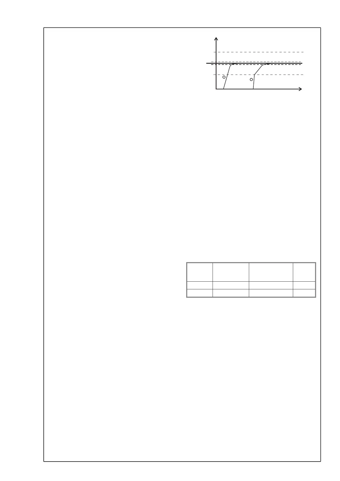
2. Shifting between two I-times. The reason for
working with two I-times is often that outside a
set pressure or flow limit you want to have a
fast response and inside a slow response (see
Fig 3). BZ: limit for switching I-time.
BZ is in % of the scaled pressure or flow
range. Half the Bz is on each side of the set
point. If the control output is not entering a
stable position, increase the I-time, you could
also try to increase the neutral zone.
Min out & Max out
The output signal from the PI-controller kan be lim
-
ited within a specified range. The range is pro
-
grammed in percent into parameter "Min out" and
"Max out".
Example: If "Min out" is set to 30,00 and "Max out" is
set to 75,00, the output signal will be limited to
3,00...7,50 V (with 0...10 V setting) or 8,8...16,0 mA
(with 4...20 mA setting).
Hand position
Return to start menu and select the menu displaying
the PI-controller together with either the pressure or
flow value.
“Flow / dP”
“Auto 50.00 % “
Press PGM, “Auto” will shift to “Hand” and make it
possible to set the output in % with ¹¸ .
To return to “Auto” press PGM.
To return to start menu press ESC.
8. Purging unit
62 Mode OFF
ON
TEST
63 On Time [s] 0...99
64 Pause [s] 30...3600
The purging function can be programmed in three
different states, OFF, ON or TEST -mode. "OFF" will
result in a inactivated mode. In "ON" mode the purg
-
ing function is activated and cleaning will be per
-
formed with even intervals. If the parameter is set to
"TEST", the purging function is active and will per
-
form constantly. This is used to check the purging
function.
In parameter "On Time" it is possible to set the time
for each interval to be during purging. The time is
programmed in seconds. Parameter "Pause" is
used to set the time between each purging. This pa
-
rameter is also programmed in seconds, 3600 sec
-
onds = 1 hour.
During the pause, the LED "Normal" is lit. Measure
-
ment and control are in operation. Two seconds be
-
fore the purging begin, the LED "Normal" goes out
and the measurement is stopped with the latest
read value stored and the control output signal is
frozen at the current level. When the purging begin,
7
© AB MICATRONE 2009-02-12 [H:\ Apps \ Typeset \ Mima \ Mi-261gb_090212.vp]
DP/Flow
BZ
BZ
Setpoint
NZ
NZ
1
2
I-time BZ
I-time
I-time
sec.
Fig 3
I-time, Itime BZ, BZ and NZ
 Loading...