EasyManua.ls Logo

Microgate SyncLink GT2E - Page 15

Microgate SyncLink GT2E
18 pages
Print Icon
To Next Page IconTo Next Page
To Previous Page IconTo Previous Page
Loading...
X.21
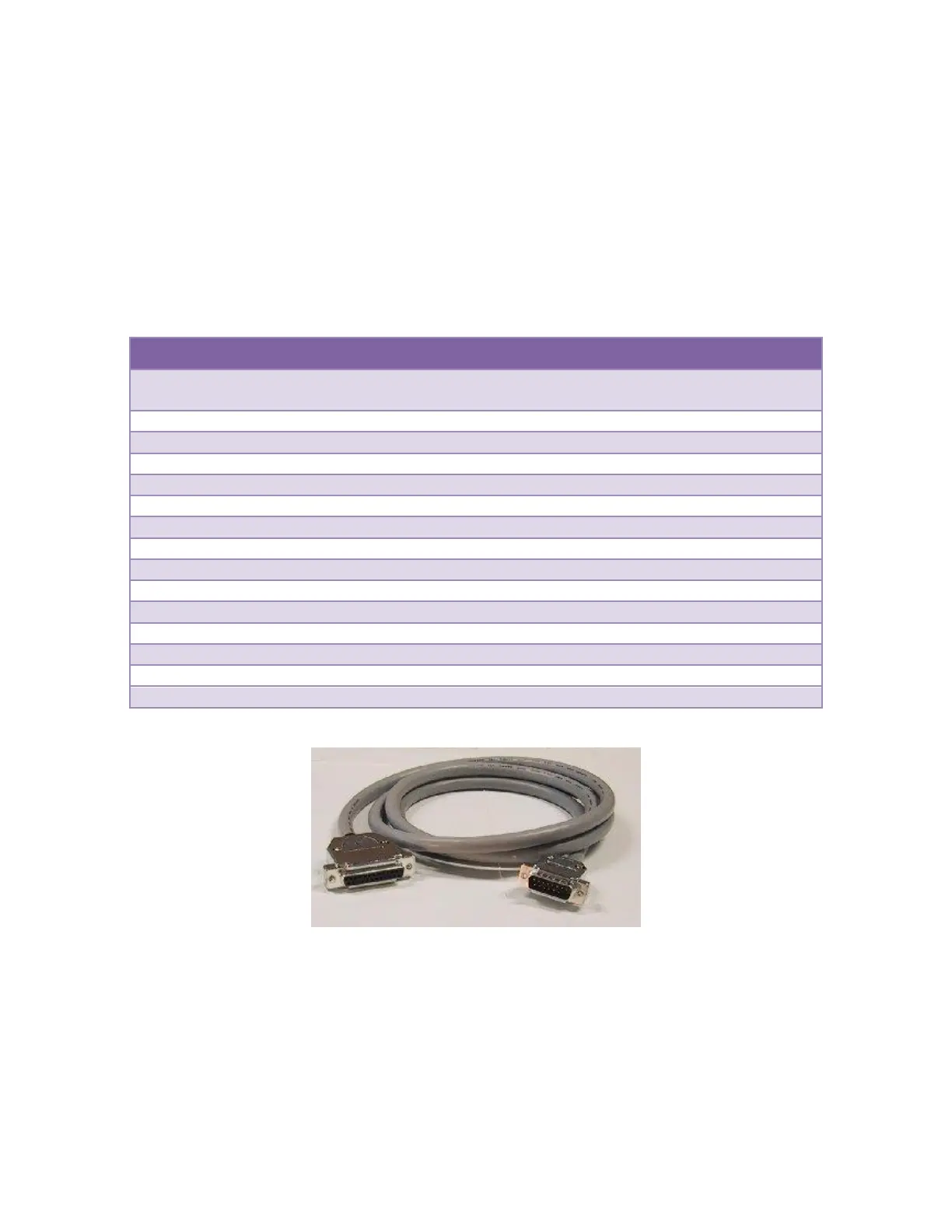
X.21 is an interface standard using differential signals on a DB-15 connector. To use this standard, install
the RS-422/485 jumpers on a port and use the MicroGate X.21 cable (Part # 2515FM).
The X.21 signal names are different than those used by the adapter and other interface standards. The
mapping of the X.21 signals to the adapter signals are shown in the table below.
The maximum data rate supported by the adapter when using X.21 is 10Mbps. Cable length and signal
loading may reduce the maximum usable data rate from this value.
X.21 Male DTE
Signal Name
Electrical Desc
DB25
Pin #
DB15
Pin #
Direction
Earth/Shield Ground
1
1
T(-/A), Transmit Data
RS-422/V.11
2
2
Output
R(-/A), Receive Data
RS-422/V.11
3
4
Input
I(-/A), Indicator (DSR/DCD)
RS-422/V.11
6,8
5
Input
Signal Ground
7
8
S(+/B), Clock Input (TxC, RxC)
RS-422/V.11
9,12
13
Input
I(+/B), Indicator (DSR/DCD)
RS-422/V.11
10,22
12
Input
X(+/B), Clock Output (AuxClk)
RS-422/V.11
11
14
Output
T(+/B), Transmit Data
RS-422/V.11
14
9
Output
S(-/A), Clock Input (TxC, RxC)
RS-422/V.11
15,17
6
Input
R(+/B), Receive Data
RS-422/V.11
16
11
Input
C(-/A), Control (DTR)
RS-422/V.11
20
3
Output
C(+/B), Control (DTR)
RS-422/V.11
23
10
Output
X(-/A), Clock Output (AuxClk)
RS-422/V.11
24
7
Output
Figure 9 X.21 Cable (Part# 2515FM )

Related product manuals