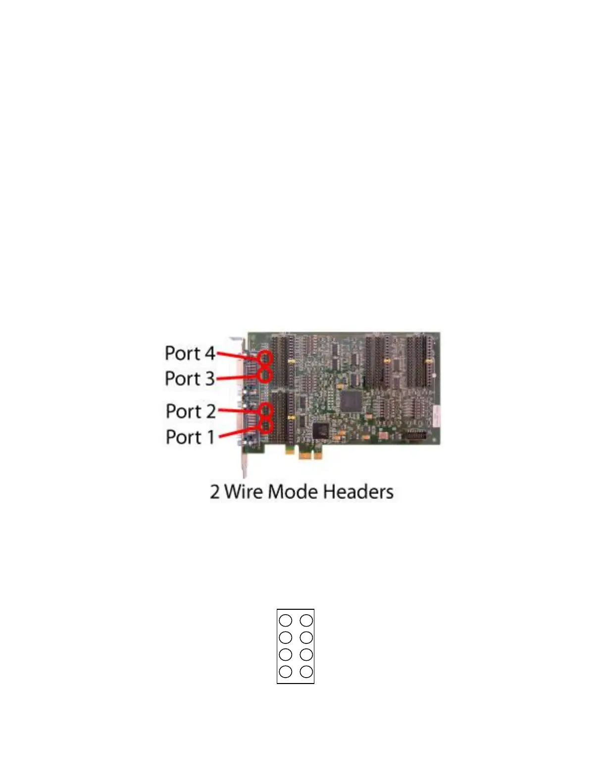
2 Wire Mode Jumpers
Some RS-485 applications use a single differential wire pair to carry data instead of separate pair for
transmit and receive data. This arrangement is sometimes called ‘2 wire’ and is useful for minimizing
wiring for connecting multiple end points. Only one end point sends data at any time, and all other end
points can receive the data.
The GT4e card by default has separate transmit and receive data signals on different pins of the serial
connector. Jumpers can be installed to connect transmit and receive pins together for use in a 2 wire
environment. The jumpers are located next to the serial connector and are labeled with the port
number and the text ‘2 WIRE’.
WARNING
The 2 wire jumpers should never be installed on ports configured for RS-232 to avoid damaging the
card. The jumpers should only be installed when configured for RS-422/RS-485 and the application
requires a common cable pair for transmit and receive data.
Jumpers are placed horizontally across the header pins. Each signal requires two jumpers to connect the
two conductors of each differential pair. The drawing below identifies the header pins. Usually only TxD
and RxD are connected (jumpers installed across pins 1 - 2 and 3 – 4).