EasyManua.ls Logo

Microgate SyncLink GT2E - Page 17

Microgate SyncLink GT2E
18 pages
Print Icon
To Next Page IconTo Next Page
To Previous Page IconTo Previous Page
Loading...
GPIO Pin Assignments
Pin #
Description
1
Ground
2
GCK0 Dedicated special purpose LVTTL
input Leave unconnected
3
GPIO[6]
4
GPIO[0]
5
GPIO[7]
6
GPIO[1]
7
GPIO[8]
8
GPIO[2]
9
GPIO[9]
10
GPIO[3]
11
GPIO[10]
12
GPIO[4]
13
GPIO[11]
14
GPIO[5]
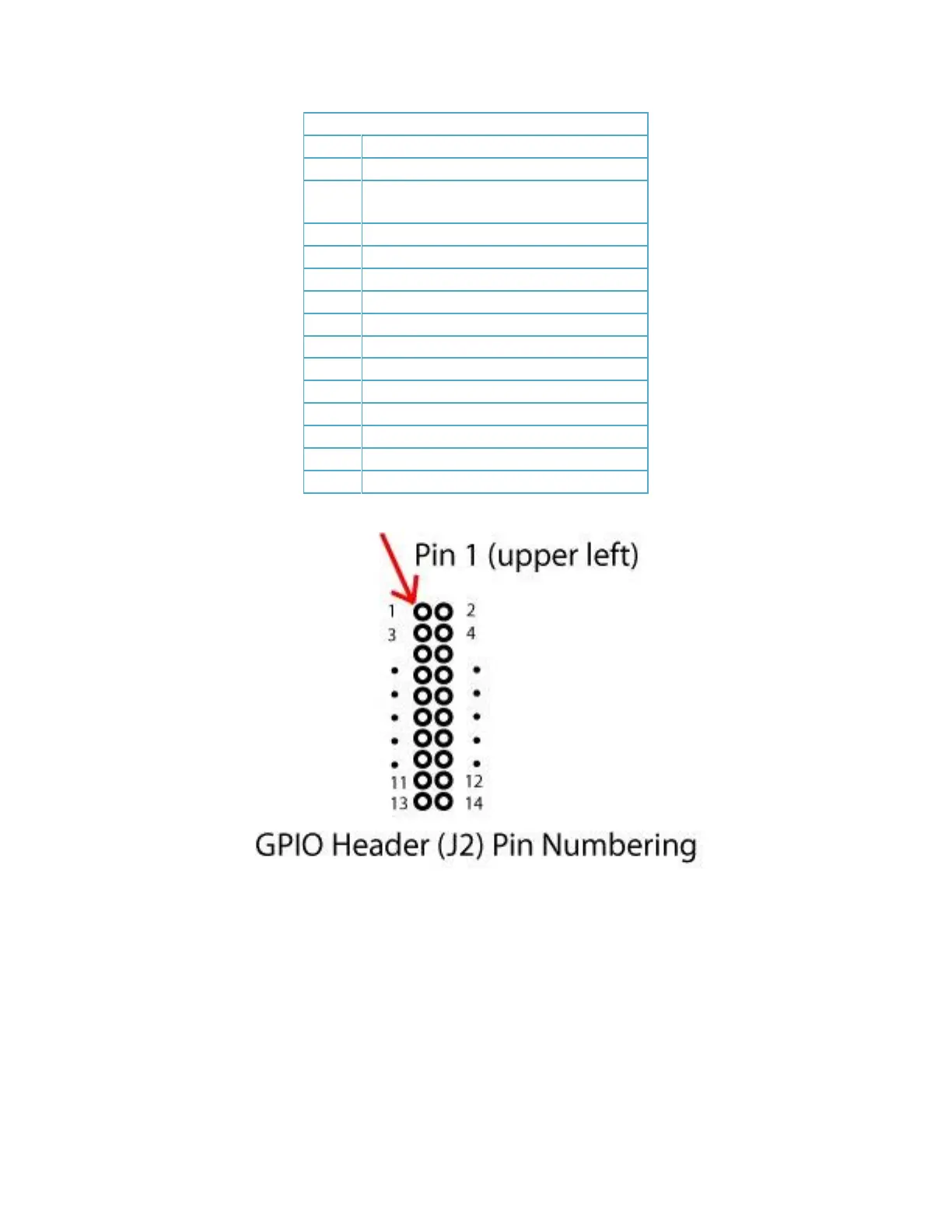
The GT adapter has a total of 12 general purpose I/O signals (GPIO[0] to GPIO[11]). By default on power
up all GPIO signals are configured as inputs (direction control = 0). Refer to the serial API documentation
for details on configuring and using GPIO signals.
WARNING: Take care when connecting to GPIO signals to prevent damage to the serial card. Outputs
should only be connected to inputs and not other outputs. Voltage limits as shown above should not be
exceeded.

Related product manuals