microHAM © 2016 All rights reserved
3 - PANEL DESCRIPTION
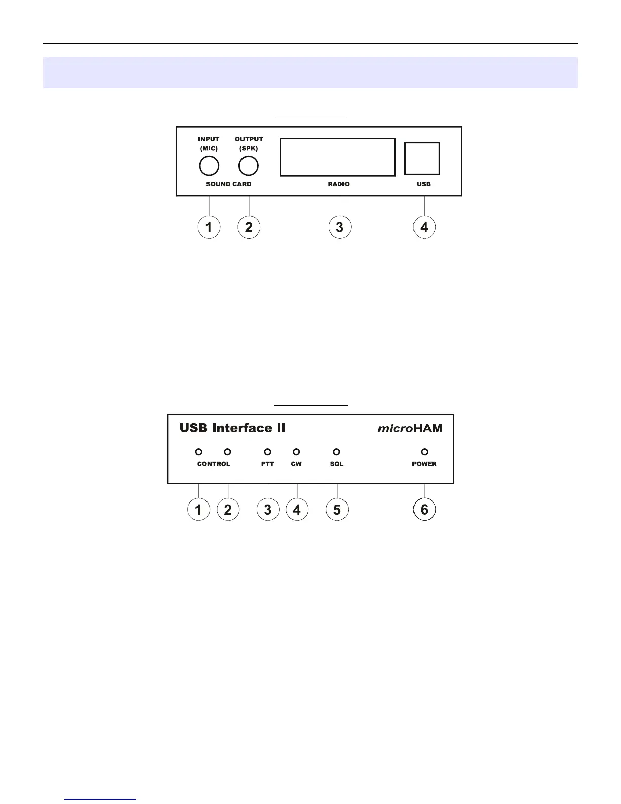
Rear Panel
(1) – INPUT (MIC): 3.5mm (1/8") jack – connects to sound card Line In or microphone
TIP – Signal, RING – NC, SHELL - Signal Ground
(2) – OUTPUT (SKP): 3.5mm (1/8") jack – connects to sound card Line Out or speaker
TIP – Signal, RING – NC, SHELL - Signal Ground
(3) - RADIO: DB15F connector for radio interconnection – a detailed description is in Appendix A
(4) - USB: USB B connector for computer connection. Connect a standard USB A-B cable.
Front Panel
(1) – CONTROL: RED color indicates when radio sends data to computer
(2) – CONTROL: GREEN color indicates when computer sends data to radio
(3) – PTT: RED color indicates when PTT is active
(4) – CW: RED color indicates when CW is active
(5) – SQL: GREEN color indicates when squelch is active
(6) – POWER: YELLOW color indicates when unit is powered
4