MHX-920 Operating Manual: Appendix C Sample Schematic Diagram 49
C. Sample Schematic Diagram
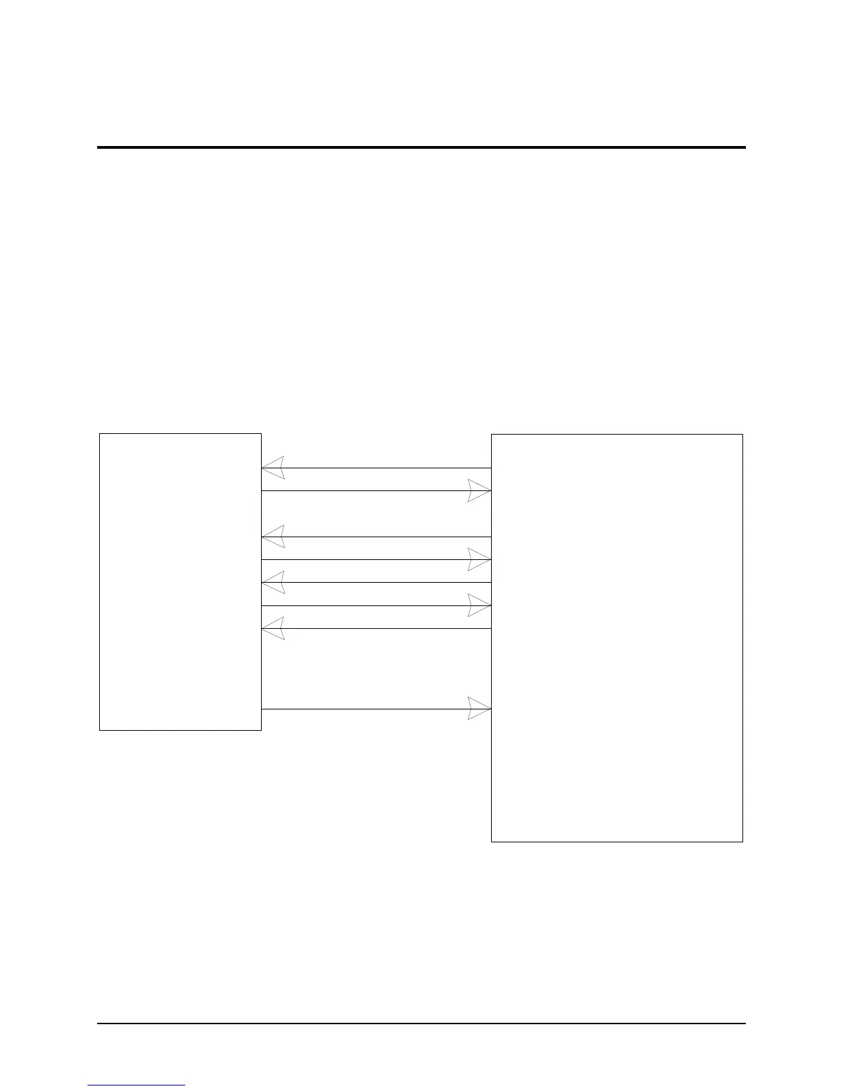
The following is a sample microprocessor implementation with a MICROCHIP PIC 16C74 and the MHX-920. The MHX-920
performs no level shifting on the serial port, so direct connection to the host microprocessor is possible.
DO NOT CONNECT THE MHX-920 TO RS 232 DRIVER OUTPUTS. DAMAGE TO THE UNIT MAY RESULT.
On this implementation, the onboard SCI of the PIC 16C74 is directly connected pins 2 and 3 of the MHX-920. The bi-
directional Port D is used for asserting or monitoring control signals from the MHX-920.
The RESET signal is a momentary active low signal asserted by the host microprocessor.
RESET initializes the MHX-920 and places the system in a known state. This signal should be set high after the host
microprocessor has been reset.
Power Connections not shown