Since 1965
MicroMetl
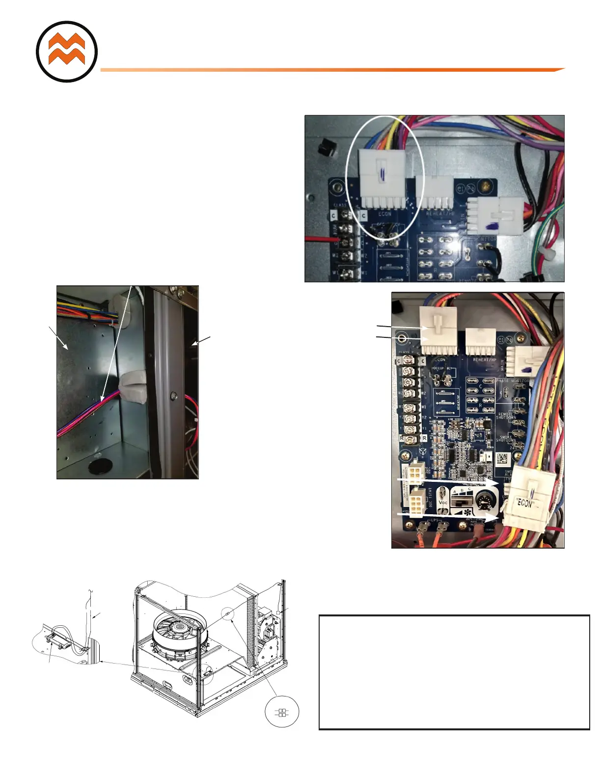
Step 11: Unplug the 12-pin male ECON plug currently
connected to the top left plug on the Unit Control Board
(UCB) and attach the 12-pin male plug labeled ECON
from the Honeywell controller to the UCB board port labeled
ECON. See Figure 6 &7.
Step 12: Connect the 12-pin male ECON plug removed from
UCB to the 12-pin female plug labeled ECON-A from the
Honeywell controller harness. See Figure 6 & 8.
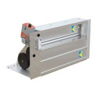
Step 13: Route the 4 sensor wires (orange, brown, violet, and
pink) into the blower section as shown in Figure 9.
Step 14: Install the Mixed Air Sensor in the blower section.
a. Screw 9901-2021 (C7250) mixed air sensor to the left
side edge of the blower through pre-punched holes.
b. Connect the orange and brown wires into the MAT
sensor routed from the control.
See Figure 10.
Figure 7 – Unplug ECON plug from Unit
Figure 8 – Plug 12 Pin ECON plug into
removed Unit Control Board (UCB) 12 Pin Plug
and Connect 12-Pin Controller Plug to
Unit Control Board
RTU UCB
12-Pin M
ale Plug
Economizer
12-Pin Male Plug
ECON
UCB 12-Pin Female Plug
Economizer 12-
Pin Female Plug
ECON-A
Control
Box
Indoor
Blower
Section
Figure 10– Mixed Air Sensor Installation W7220
(Vane Axial Fan System).
W7220 MAT
Sensor Ref
To Control Box
Bundle these
connections
into the
corner post
with wire tie
PL6 Ref
ORG
BRN
PNK
VIO
PNK
VIO
ATTENTION:
1 - The controller's wiring harness is designed specifically for EcoBlue, Axiom-Fan
and X-Vane units with the Unit Control Board (UCB). If your unit has the older
Central Terminal Board (CTB) or Centrifugal Supply Blower then you
must purchase a different harness
(MicroMetl P/N 9962-0407 & 9962-0407-SAOAEXT,
NV Customers order P/N1002-0407).
2 - If you have a 48/50JC 04-07 unit with System VU, these controls will
not work properly. Please let your distributor know that you will need
an ECD-SRT12CB-D0DB-4 economizer.
4 Sensor Wires
Figure 9 – Route 4 Sensor Wires to Indoor
Blower Section