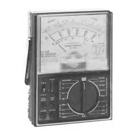
RESISTANCE
MEASUREMENTS
BEFORE TAKING
ANY RESISTANCE
MEASUREMENTS,
DISCON-
NECT POWER
TO THE
UNIT UNDER TEST
AND DISCHARGE THE
CAPACITORS. It is
best to remove batteries
and unplug line
cords.
1
.
Plug
the test leads
into the
Q
COM and
©
V-S2-A
jacks.
2.
Leave the range doubler
switch in the
V-I2-A
position. Set the range
switch to one of the £2
positions; touch the
test probe tips together
and
adjust the OHM ADJ. control
to bring the pointer
to
"0"
on the
top
(green)
OHMS scale.
3.
Now,
connect the probe tips across the
circuit or part
under test.
4.
Read
the resistance
on the green OHMS
scale; use the proper multiplier
to obtain
the correct
value (R "times"
1, 10,
100, 1000, or
10,000
depending on the position of the range
switch).
Notes: When you
are unable to adjust the pointer
to
"0"
on the
OHMS
scale
in the R x
1,
R x
10, R
x
100 or Rx1K positions, the
penlight bat-
tery
must
be replaced.
When you are unable
to adjust the pointer to
"0"
on
the OHMS
scale when in the R x 10K
position, replace the 9-volt bat-
tery. When measuring resistance,
it is best
to disconnect one side of the
part under test
(so the remainder of the circuit
will not interfere with
the
readings).
THE RANGE
DOUBLER SWITCH
MUST BE LEFT IN
THE
V-I2-A
POSI-
TION
FOR
ALL RESISTANCE
MEASUREMENTS.
-
7
-