EasyManua.ls Logo

Micronta 22-204C - User Manual

Micronta 22-204C
11 pages
Print Icon
To Next Page IconTo Next Page
Loading...
MICRO
NTA®*
50,000 OHMS/VOLT MULTITESTER
with Range Doubler
INSTRUCTION
MANUAL
22-204C
"°iD:
VARKS OF RADIO SHACK
I
.
?
ON TANDY CORPORATION
Question and Answer IconNeed help?

Do you have a question about the Micronta 22-204C and is the answer not in the manual?

Summary

Specifications

Ranges

Lists the available measurement ranges for the multimeter.

DC Voltage Specifications

Details the DC voltage measurement capabilities and ranges.

AC Voltage Specifications

Details the AC voltage measurement capabilities and ranges.

DC Current Specifications

Details the DC current measurement capabilities and ranges.

Resistance Specifications

Details the resistance measurement capabilities and ranges.

Decibel Specifications

Details the decibel measurement capabilities and ranges.

Accuracy Specifications

Provides accuracy details for AC and DC measurements.

Sensitivity Specifications

Outlines the sensitivity for DC and AC voltage/ohm measurements.

Device Components and Maintenance

Details on meter movement, batteries, test leads, and fuse requirements.

Using Your Multitester

Battery Installation and Maintenance

Instructions for installing and maintaining batteries, including removal when not in use.

Techniques for Accurate Readings

Guidance on meter placement, reading the scale, and avoiding parallax errors.

Pointer Zero Adjustment

Procedure to adjust the meter pointer to zero on the OHMS scale.

Polarity and Input Limits

Correct test lead polarity and maximum input limits for voltage and current.

Range Doubler Switch Operation

How to use the range doubler switch for different measurements.

Special Panel Markings Explanation

Common Input Terminal Warning

Warning about connecting the common terminal to sources exceeding 500 volts.

High Voltage Measurement Caution

Cautionary advice for making high voltage measurements, avoiding touching terminals.

Reference to Operating Instructions

Indicates that further operating instructions are provided.

DC Voltage Measurements

Test Lead Connection for DC Voltage

Instructions for plugging test leads into the correct jacks for DC voltage measurements.

Setting DC Voltage Range

Guidance on selecting the appropriate DC voltage range switch setting.

High Voltage DC Range Settings

Specific instructions for setting range and range doubler for 250V to 1000V DC.

AC Voltage Measurements

Test Lead Connection for AC Voltage

Instructions for plugging test leads into the correct jacks for AC voltage measurements.

Setting AC Voltage Range

Guidance on selecting the appropriate AC voltage range switch setting.

Reading AC Scale

Instructions on how to read AC voltage values from the meter's scale.

Resistance Measurements

Safety Warning for Resistance Measurements

Warning against applying voltage while in resistance mode and discharging capacitors.

Resistance Measurement Setup

Connecting test leads and setting range doubler for resistance readings.

Zero Ohm Adjustment

Procedure to adjust the OHM ADJ. control to zero the pointer for resistance.

Reading Resistance Values

How to read resistance on the green OHMS scale using the correct multiplier.

Battery Check for Zero Adjustment

Notes on checking batteries when unable to adjust the pointer to zero.

Range Doubler for Resistance Use

Instruction to keep the range doubler switch in V-Ω-A for resistance measurements.

DC Current Measurements

Safety Warning for Current Measurements

Warning against applying voltage while in current mode.

DC Current Measurement Setup

Plugging leads and setting the range switch for DC current measurement.

Circuit Connection for Current

How to open the circuit and connect the leads for current measurement.

Reading DC Current Values

How to read DC current on the black DC scales, considering range doubler.

Decibel Measurements

Decibel Measurement Setup

Plugging leads and setting range and range doubler for dB readings.

Reading Decibel Values

How to read dB values and add appropriate numbers from the meter chart.

Absolute dB Measurement Note

Note on circuit impedance requirement for absolute dB measurements.

Battery and Fuse Replacement

Safety Warnings for Replacement

Warnings to avoid shock, disconnect terminals, and use specified replacements.

Fuse Replacement Caution

Caution to replace the fuse only with a 0.75A, 250V rating for fire protection.

Battery and Fuse Replacement Steps

Step-by-step instructions to install or replace the battery or fuse.

Cabinet Closure Warning

Warning not to operate the unit until the cabinet is fully closed.

Good Meter Measurement Practices

General Voltage Hazard Caution

Caution about the possibility of dangerous voltages and high voltage at unexpected points.

Environmental Precautions

Advice on avoiding wet floors, grounded objects, and working near them.

Test Lead Safety

Use only insulated test leads and avoid touching bare metal parts.

Discharging Capacitors

Discharge filter capacitors before connecting test leads due to stored charges.

Incorrect Function Measurement

Avoid measuring voltage/current with the function set to resistance or vice versa.

Vibration and Shock Avoidance

Avoid vibration or mechanical shock which may damage the meter or affect accuracy.

Schematic Diagram

Overview

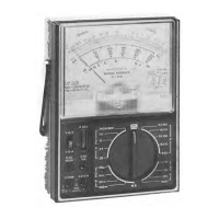
The Micronta 50,000 Ohms/Volt Multitester with Range Doubler, model 22-204C, is a versatile analog multimeter designed for measuring various electrical parameters. Its primary function is to provide accurate readings for DC voltage, AC voltage, DC current, resistance, and decibels, making it suitable for a wide range of electronic troubleshooting and measurement tasks. A key feature is its "Range Doubler" switch, which effectively expands the measurement capabilities by dividing the selected range by two for certain functions, offering greater flexibility in reading values.

Function Description:

The multitester measures:

  • DC Voltage: Ranges from 0-125mV up to 1000 volts.
  • AC Voltage: Ranges from 0-5 volts up to 1000 volts.
  • DC Current: Ranges from 0-25µA up to 10 amperes.
  • Resistance: Ranges from 0-2K ohms up to 20 Megohms, with a center scale of 10 ohms.
  • Decibels: Ranges from -20 to +62 dB across 8 ranges.

Important Technical Specifications:

  • Ranges: 43 distinct ranges for various measurements.
  • DC Voltage Sensitivity: 50,000 ohms/volt (V-A/2) or 25,000 ohms/volt (V-Ω-A).
  • AC Voltage Sensitivity: 10,000 ohms/volt (V-A/2) or 5,000 ohms/volt (V-Ω-A).
  • Meter Movement: Features a 4-1/4" (10.8 cm), 3-color, mirrored scale with an 18µA full scale deflection, aiding in precise readings by minimizing parallax error.
  • Accuracy:
    • ±3% for DC measurements (except as noted).
    • ±4% for AC measurements, and for 125mV to 2.5 volts, and 500 to 1000 volts DC.
    • ±3% of scale length on resistance measurements.
  • Batteries: Requires one type AA penlight cell for most resistance ranges and one 9-volt rectangular type battery for the 20 Megohm resistance range.
  • Leads: Supplied with 44" (110 cm) banana plug style test leads.
  • Fuse: Protected by a 0.75A 250V fuse.

Usage Features:

  • Range Doubler Switch: This unique feature allows for expanded measurement capabilities. When the switch is in the V-A/2 position for functions other than resistance, the selected range switch setting is divided by 2. For example, a 250 AC V setting with the range doubler in V-A/2 becomes a 125-volt range. For resistance readings, the range doubler switch must always be in the V-Ω-A position.
  • Scale Reading: For accurate readings, the user should view the scale from a position where the pointer and its reflection on the mirror align, eliminating parallax errors. The meter should be placed flat on a non-metallic surface.
  • Optimal Reading: For the most accurate results, the range and range doubler switch settings should be chosen such that the reading falls within the upper 1/3rd of the meter scale.
  • Zero Adjustment: A plastic screw in the lower center of the meter face allows for mechanical zero adjustment of the pointer. For resistance measurements, the OHM ADJ. control is used to bring the pointer to "0" on the OHMS scale after touching the test probe tips together.
  • Polarity: When making DC measurements, correct test lead polarity must be observed: black lead into the COM jack and red lead into the V-Ω-A (or DC 1000V or DC 10A) jacks.
  • High Voltage Caution: Extreme caution is advised when measuring voltages of 150V and above. Special panel markings serve as safety reminders, indicating that the common input terminal should not be connected to sources exceeding 500 volts with respect to earth/ground, and to avoid touching terminals or probe ends during high voltage measurements.
  • Maximum Input Limits: The maximum input limit for voltage and current measurement between V-Ω-A and COM is 1000V AC, 250V DC, and 500mA DC.
  • Starting Measurements: When measuring unknown voltages or currents, it is recommended to start with the highest available range and work downwards to prevent damage to the meter.
  • Resistance Measurement Procedure: Before taking resistance measurements, power to the unit under test must be disconnected, and capacitors discharged. Batteries should ideally be removed, and line cords unplugged. The range doubler switch must be in the V-Ω-A position.
  • Decibel Measurements: For absolute dB measurements, the circuit impedance must be 600 ohms. 0 dB is defined as 1 milliwatt dissipated in a 600 ohm impedance (equivalent to 0.775 volts across 600 ohms).
  • Meter Connection: Voltage and resistance measurements are made with the meter connected in parallel, while current measurements are made with the meter connected in series.

Maintenance Features:

  • Battery Replacement: The multitester requires one 9-volt battery for the 20 Megohm range and one AA penlight cell for other resistance ranges. If the pointer cannot be adjusted to "0" on the OHMS scale, the respective battery needs replacement.
    • For R x 1, R x 10, R x 100, or R x 1K positions, replace the AA penlight battery.
    • For R x 10K position, replace the 9-volt battery.
  • Fuse Replacement: The device is protected by a 0.75A 250V fuse. If the fuse blows (e.g., when voltage is applied in resistance or current mode, resulting in no meter movement), it must be replaced with the same type/rating.
  • Battery Care: To prevent damage from leaking chemicals, weak or dead batteries should never be left in the unit. If the unit is not used for a week or more, batteries should be removed.
  • Cabinet Access: To replace batteries or the fuse, the back cover must be removed by loosening three screws. Users are warned not to touch any area inside other than the battery or fuse. The unit should not be operated until the cabinet is fully closed.
  • Test Leads: Only the same type of test leads supplied with the unit should be used. Replacements are available from Radio Shack stores. Test leads with frayed or broken insulation should never be used.
  • Environmental Care: The meter should not be exposed to moisture, high humidity, excessive dust, or dirt. It should also be protected from vibration, mechanical shock, and strong magnetic fields, as these can affect its accuracy or cause damage.
  • Power Off When Not in Use: The range switch should always be left in the OFF position when the meter is not in use.

Micronta 22-204C Specifications

General IconGeneral
BrandMicronta
Model22-204C
CategoryTest Equipment
LanguageEnglish

Related product manuals