38 Operation and Menu Structure
_______________________________________________________________________________________________
_______________________________________________________________________________________________
MICROPLEX Operator’s Manual SOLID F40 Edition 1.1
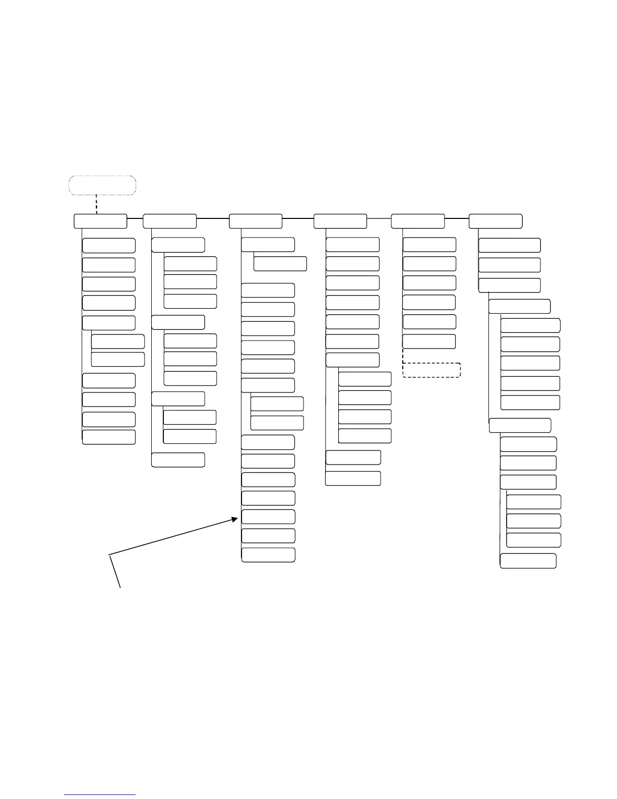
4.6. Menu Structure
Access to the menu structure is possible as soon as the printer is turned OFF LINE.
The SOLID F40 menu structure is arranged in different levels:
Menu Level 1
Status Shee
Hexdump
Normal Print/FF
Cancel Job
Menu Page
Sliding Pattern
Buffer-Dump
Paper Menu
Page Length
in mm
Two
Up Mode
Conf igur ation
Interface
SIA Timeout
Emulation
Languag
Input Buffer
Transparent Cod
Config. Word
User Config.
elec
Defin
Factory Defaul
Page Menu
Font Number
Or ientat ion
Margin
Left
from Right
Top
from Bottom
Engin
Y
Direction
Print Direction
X-Direction
PCL Y-Offset
ON LINE - Mode
OFF LINE
in inch
Line Spacin
Symbol Cod
Key lock
Time Setting
Date Setting
Char. Spacing
Ne t w o r k
Font Lis
Extended Menu
in 1/300 inch
Paper Width
in mm
in inch
in 1/300 inch
Service Mod
Key ton
RFM
Line Termination
Resolution
Image X
Pos.
Image Y
Pos.
Format Check
Last Error
DHCP
Manual
Off
IP Address
ubnet
ask
atewa
IP Assign
10MB HalfDuplex
10MB FullDuplex
Autonegot iation
Duplex/Speed
100MB HalfDu
lex
100MB FullDuplex
NumberOfCopies
File Managemen
Print-Files
Directory
Print Density
Timeout
Persistent DHCP
SNMP
Ethernet
This panel function allows the user to choose a reduced menu instead of
the extended menu shown above.