PD-IM-7648 Evaluation System - User Guide
Copyright © 2013 Microsemi 8
Rev 1.0 / 25 Dec 13 Analog Mixed Signal Group
1 Enterprise, Aliso Viejo, CA 92656, USA; Phone (USA): (800) 713-4113, (ROW): (949) 221-7100 Fax: (949) 756-0308
3 2BPhysical Description
3.1 12BSwitches and Jumpers
The evaluation system comprises switches and jumpers used to select the desired configuration states of the
board. Default configurations are indicated as 'default.'
3.1.1 17BUART Communication Selection
There are three UART communication options:
USB to UART (connecting USB cable to U7).
For this connection a driver for CP210x should be installed. The driver can be downloaded
from http://www.silabs.com/products/mcu/Pages/USBtoUARTBridgeVCPDrivers.aspx
.
RS232 to UART (connecting RS232 cable to J33).
UART input (connecting UART cable to J26).
J6 on DB must be open in order to work in UART mode.
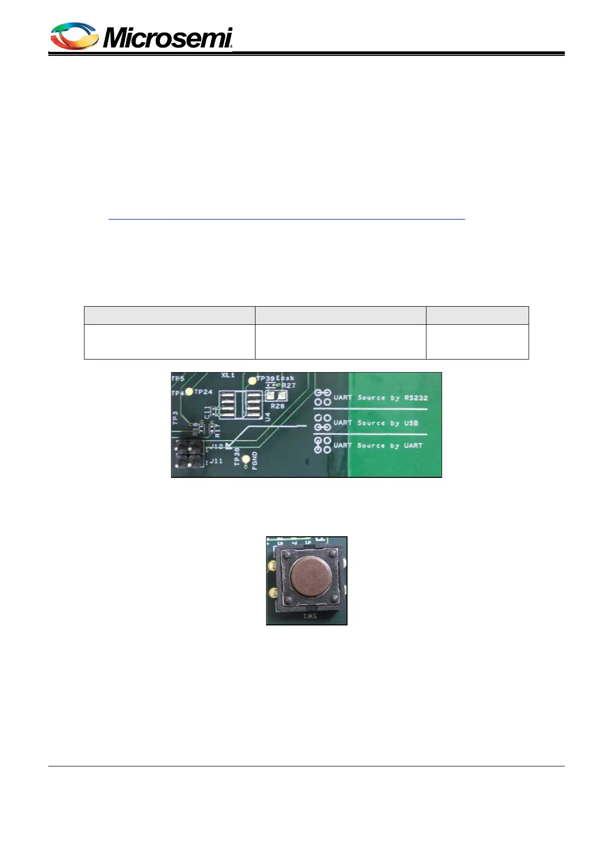
Using J11 and J12 jumpers, the following three options are available (see Table 2).
Table 2: UART Communication Selection
UART input USB to UART RS232 to UART
Short from J11 pin
2 to J12 pin 2
J11 – Short from pin "1" to "2"
J12 – N.C
J11 – N.C
J12 – Short from pin "1" to "2"
Figure 6: UART Communication Selection (J11, J12)
3.1.2 18BReset Button
The dedicated Reset push button SW1 (see Figure 7) resets DB PoE controller PD69200.
Figure 7: Reset Push Button (SW1)
3.2 13BConnectors
The following sections provide both a general and a detailed description of the board connectors.
3.2.1 19BConnectors Table
The evaluation system's connectors are listed in Table 3.