PD-IM-7648 Evaluation System - User Guide
Copyright © 2013 Microsemi 9
Rev 1.0 / 25 Dec 13 Analog Mixed Signal Group
1 Enterprise, Aliso Viejo, CA 92656, USA; Phone (USA): (800) 713-4113, (ROW): (949) 221-7100 Fax: (949) 756-0308
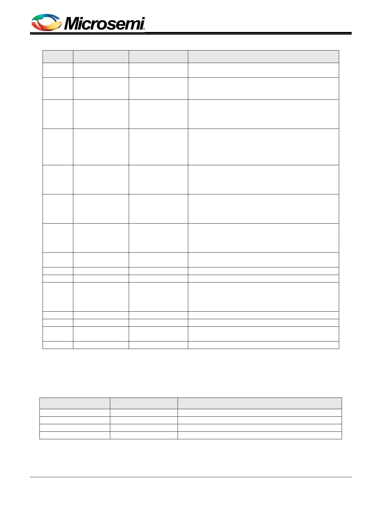
Table 3: Connector List
Number Connector Name Description
1 MB: J29-J32 RJ45 Connectors
48 'RJ45' ports connecting MB to Powered Device
load.
2
MB: J22-J25
DB: J11-J14
Port Connection
Port connection (Vport_pos and Vport_neg)
between MB and DB implemented by using four
3
J17, J18
DB: J9, J10
Vin Connectors
DC in (Vmain) connection used to power MB and
DB Evaluation systems.
4
MB: J2, J3
DB: J4, J7
Communication
and Indication
Communication (UART, I
2
C and ESPI) and
indication signals (reset, disable, etc) running
between MB and DB, using flat cables connected
to J2 (PoE domain) and J3 (Host Domain)
5 MB: J4
Isolated External
HOST
Control and indication signals running between an
external hosting system and MB (Host Domain on
the daughterboard), of limited use as most of the
communication is via USB, UART, and RS232.
6 MB: U7 Isolated USB
USB communication coming from hosting system
(U7), converted to UART or I
2
C communication
and directed to DB (Host Domain on
7 MB: J33 Isolated RS232
RS232 signal levels coming from the hosting
system (J33) and converted to UART signal levels,
then directed to DB (Host Domain on
8 MB: J26 Isolated UART
UART interface from hosting system and MB, then
directed to DB (Host Domain on daughterboard).
11 MB: J1
External Power
Supplies
'Power Good' indication signals coming from power
supplies, indicating operating/failed power supply
status. It is also a hot-swap signal for hot
swappable PoE applications.
14 DB: J1 LED Stream
Port's status presented via LEDs indication signals
running to LED board.
PoE Controller burning interface
3.2.2 20BConnectors Detailed Explanation
The numbering is in reference to the numbers given in Table 3.
1. RJ45 Connectors (see Figure 8)
There are four dedicated RJ45 connectors; each contains 12 RJ45 ports.
Pin No. (Each RJ45) Signal Name Description
The PoE's Positive spare port
The PoE's Negative spare port
The PoE's negative data port
The PoE's positive data port
Manufacturer: FOXCONN
Manufacture part number: JM371B3-KD10-4F