PD-IM-7648 Evaluation System - User Guide
Copyright © 2013 Microsemi 10
Rev 1.0 / 25 Dec 13 Analog Mixed Signal Group
1 Enterprise, Aliso Viejo, CA 92656, USA; Phone (USA): (800) 713-4113, (ROW): (949) 221-7100 Fax: (949) 756-0308
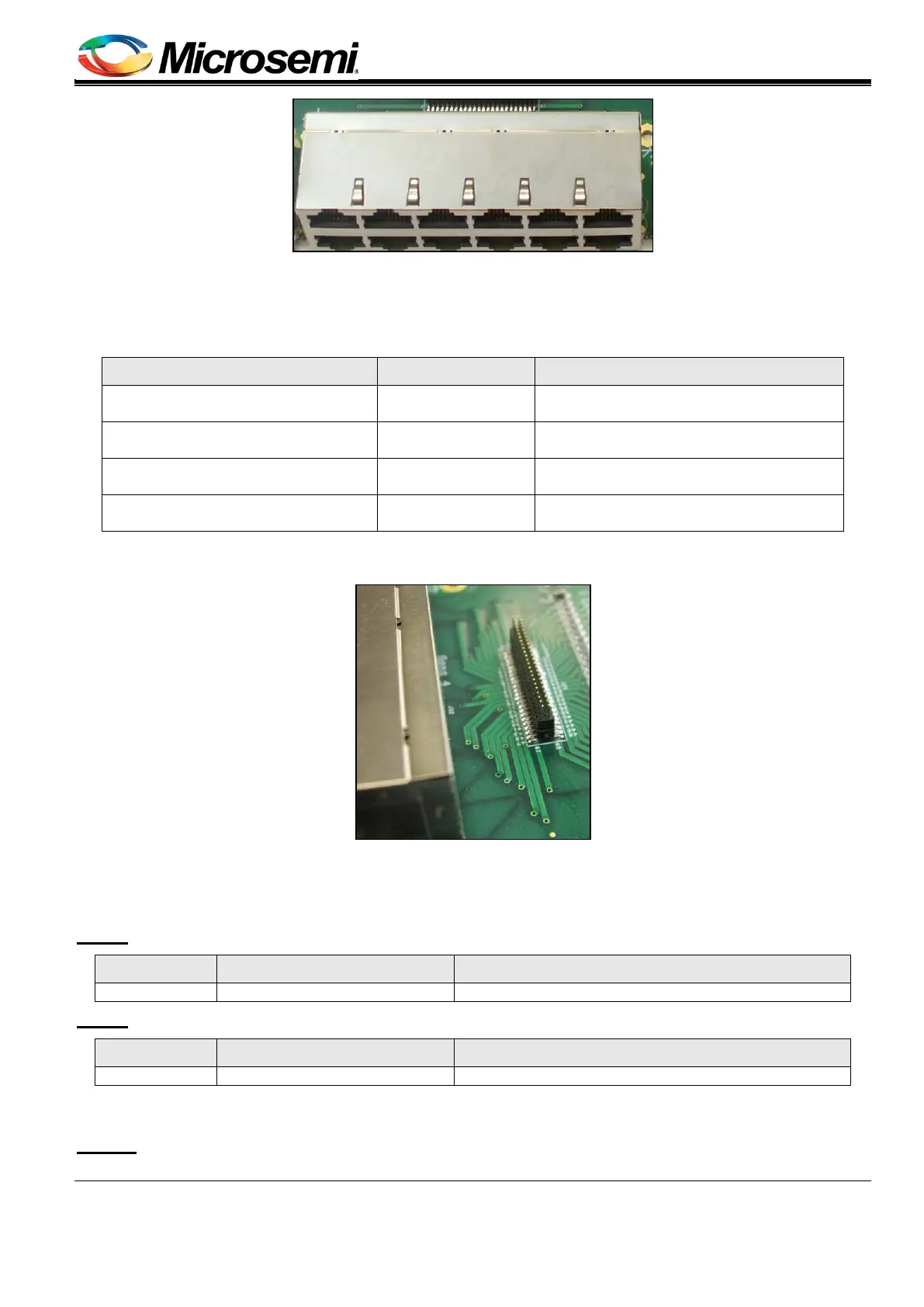
Figure 8: RJ45 Connectors
2. Port Connection (see Figure 9)
Ports Connection (spare_NEG, spare_POS, data_NEG and data_POS) between MB's RJ45 and DB PoE circuitry
is utilized by four connectors.
Pin No. Signal Name Description
1, 5, 9, 13, 17, 21, 25, 29, 33, 37,
41, 45
spare_NEGx PoE's negative spare port
2, 6, 10, 14, 18, 22, 26, 30, 34, 38,
42, 46
spare_POSx PoE's positive spare port
3, 7, 11, 15, 19, 23, 27,31, 35, 39,
43, 47
data_NEGx PoE's negative data port
4, 8, 12, 16, 20, 24, 28, 32, 36, 40,
44, 48
data_POSx PoE's positive data port
Manufacturer: CviLux
Manufacture part number: CH57482M100-PA
Figure 9: Port Connection
3. Vin Connectors (see Figure 10)
DC in (Vmain) connection, used for powering the MB and DB Evaluation systems. 44 VDC > Vmain> 57 V DC.
MB: J6
Pin No. Signal Name Description
Main positive voltage (referenced to AGND)
MB: J7
Pin No. Signal Name Description
Manufacturer: CviLux
Manufacture part number: CP01-316130
MB: J17