PD-IM-7648 Evaluation System - User Guide
Copyright © 2013 Microsemi 11
Rev 1.0 / 25 Dec 13 Analog Mixed Signal Group
1 Enterprise, Aliso Viejo, CA 92656, USA; Phone (USA): (800) 713-4113, (ROW): (949) 221-7100 Fax: (949) 756-0308
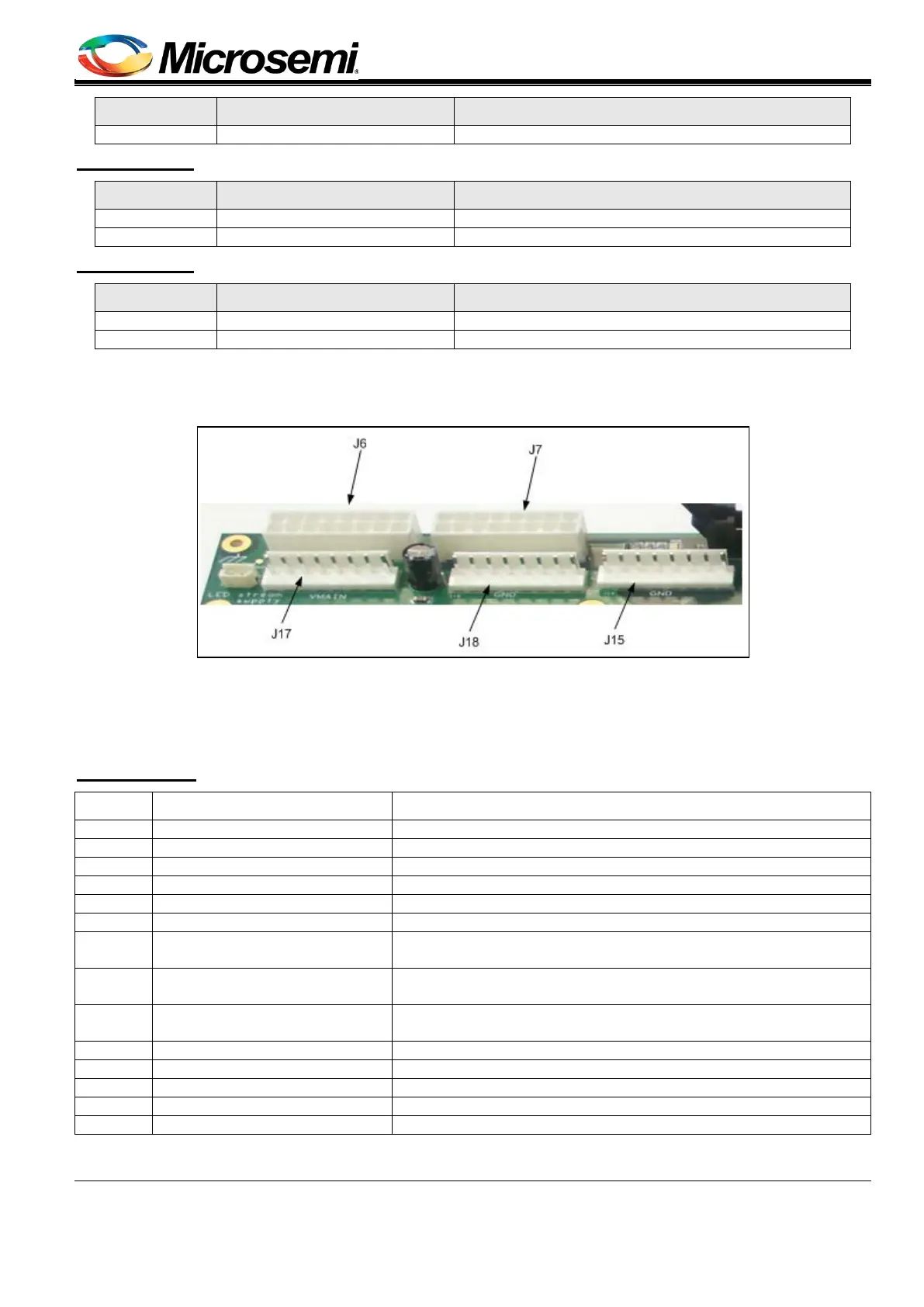
Pin No. Signal Name Description
Main positive voltage (referenced to AGND)
MB: J15, DB: J7
Pin No. Signal Name Description
Main positive voltage (referenced to AGND)
MB: J18, DB: J8
Pin No. Signal Name Description
Main positive voltage (referenced to AGND)
Manufacturer: CviLux
Manufacture part number: CI5208P1VOO
Figure 10: Vin Connectors
4. Communication and Indication (see Figure 11)
Communication (UART, I
2
C and ESPI) and indication signals (reset, disable, etc.) run between MB and DB using
flat cables connected to J2 (PoE domain) and J3 (Host Domain) connectors.
MB: J3, DB: J4
Pin No. Signal Name Description
Reset signal sent from hosting system.
Disable signal sent from hosting system.
System_ok signal sent from hosting system.
Int_out signal sent from hosting system.
7 3_3V_iso
3.3 VDC sent from hosting system (isolated from PoE domain),
referenced to 'GND_Floating.'
8, 13,
GND_Floating Hosting system ground (isolated from PoE domain)
9 UART_Tx_isolated
Tx signal (transmit), direction sent from PoE controller (3.3V
tolerate).
Rx signal (receive), to PoE controller (3.3V tolerate).
I
2
C SDA: data I
2
C signal between hosting system and PD69208
I
2
C SCL: clock I
2
C signal between hosting system and PD69208
SDA_enhanced_mode_isolated
I
2
C SDA: Data I
2
C signal between hosting system and PD69200.
SCL_enhanced_mode_isolated
I
2
C SCL: Clock I
2
C signal between hosting system and PD69200.
Manufacturer: CviLux