5
Fabric Interface Settings
By default, the hard Cortex-M3 processor is set up to access the DDR Controller. You can also allow a
fabric Master to access the DDR Controller by enabling the Fabric Interface Setting checkbox. In this
case, you can choose one of the following options:
• Use an AXI Interface - The fabric Master accesses the DDR Controller through a 64-bit AXI
interface.
• Use a Single AHBLite Interface - The fabric Master accesses the DDR Controller through a
single 32-bit AHB interface.
• Use two AHBLite Interfaces - Two fabric Masters access the DDR Controller using two 32-bit
AHB interfaces.
The configuration view (Figure 1-1) updates according to your Fabric Interface selection.
I/O Drive Strength (DDR2 and DDR3 only)
Select one of the following drive strengths for your DDR I/Os:
• Half Drive Strength
• Full Drive Strength
Libero SoC sets the DDR I/O Standard for your MDDR system based on your DDR Memory type and I/O
Drive Strength (as shown in Table 1-1).
IO Standard (LPDDR only)
Select one of the following options:
• LVCMOS18 (Lowest Power) for LVCMOS 1.8V IO standard. Used in typical LPDDR1
applications.
• LPDDRI Note: Before you choose this standard, make sure that your board supports this
standard. You must use this option when targeting the M2S-EVAL-KIT or the SF2-STARTER-KIT
boards. LPDDRI IO standards require that a IMP_CALIB resistor is installed on the board.
IO Calibration (LPDDR only)
Choose one of the following options when using LVCMOS18 IO standard:
•On
• Off (Typical)
Calibration ON and OFF optionally controls the use of an IO calibration block that calibrates the IO
drivers to an external resistor. When OFF, the device uses a preset IO driver adjustment.
When ON, this requires a 150-ohm IMP_CALIB resistor to be installed on the PCB.
This is used to calibrate the IO to the PCB characteristics. However, when set to ON, a resistor needs to
be installed or the memory controller will not initialize.
For more information, refer to AC393-SmartFusion2 and IGLOO2 Board Design Guidelines Application
Note and the SmartFusion2 SoC FPGA High Speed DDR Interfaces User Guide.
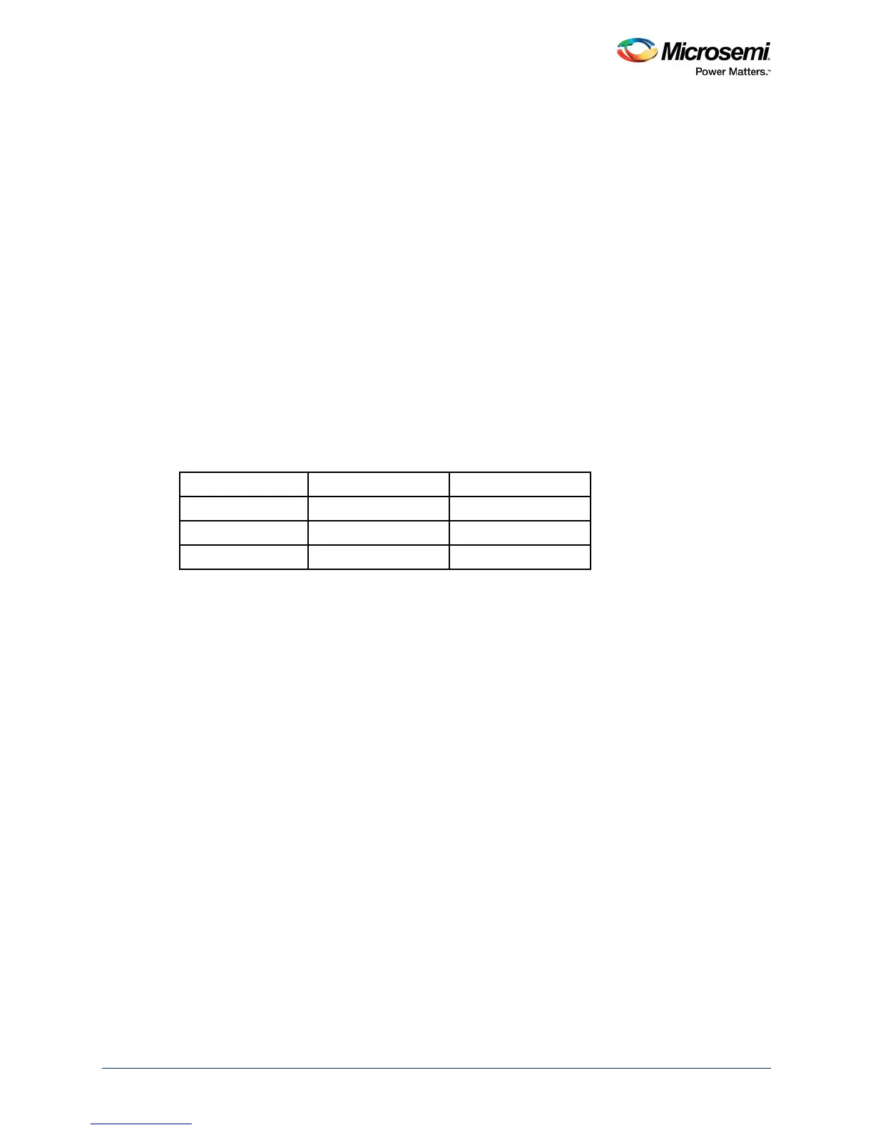
Table 1-1 • I/O Drive Strength and DDR Memory Type
DDR Memory Type Half Strength Drive Full Strength Drive
DDR3 SSTL15I SSTL15II
DDR2 SSTL18I SSTL18II
LPDDR LPDRI LPDRII
 Loading...