11
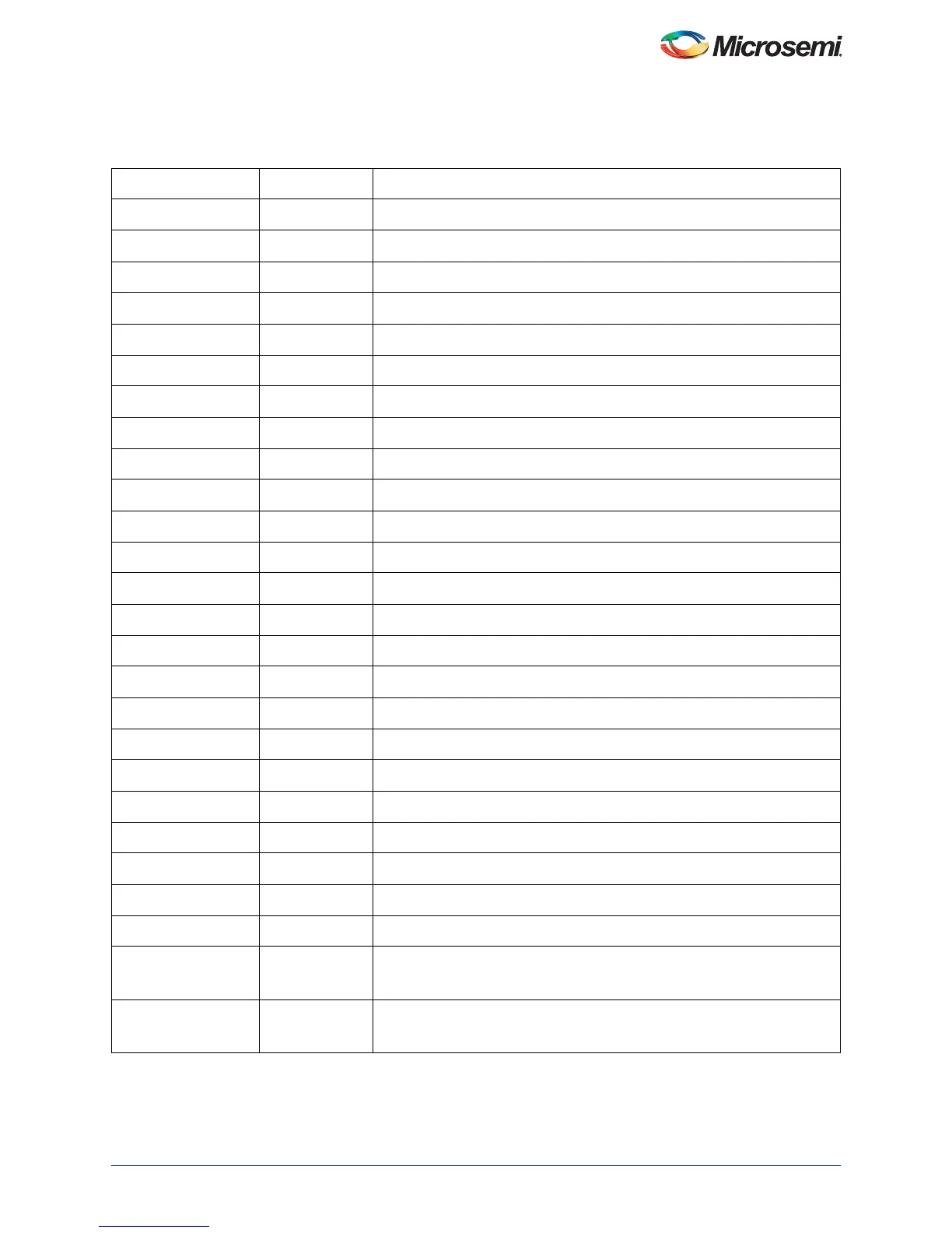
Table 3-1 lists the Hard Multiplier Accumulator port signals for Normal mode.
Table 3-1 • Hard Multiplier Accumulator Ports - Normal Mode
Signal Direction Description
A0 Input Input data A0, 2- 18 bits wide
B0 Input Input data B0, 2- 18 bits wide
C Input Input data C, 2- 44 bits wide
CLK Input Input clock for all registers
A0_ACLR_N Input Asynchronous reset for data A0 registers
A0_SCLR_N Input Synchronous reset for data A0 registers
A0_EN Input Enable for data A0 registers
B0_ACLR_N Input Asynchronous reset for data B0 registers
B0_SCLR_N Input Synchronous reset for data B0 registers
B0_EN Input Enable for data B0 registers
C_ACLR_N Input Asynchronous reset for data C, Carry In registers
C_SCLR_N Input Synchronous reset for data C, Carry In registers
C_EN Input Enable for data C, Carry In registers
CARRYIN Input Carry In input for operand C
ARSHFT17_ACLR_N Input Asynchronous reset for ARSHF T17 register
ARSHFT17_SCLR_N Input Synchronous reset for ARSHF T17 register
ARSHFT17_EN Input Enable for ARSHFT17 register
SUB_ACLR_N Input Asynchronous reset for input control SUB registers
SUB_SCLR_N Input Synchronous reset for input control SUB registers
SUB_EN Input Enable for input control SUB registers
SUB Input Input control signal to select between add or subtract operation
P_ACLR_N Input Asynchronous reset for result P, CDOUT, Overflow/Carryout registers
P_SCLR_N Input Synchronous reset for result P, CDOUT, Overflow/Carryout registers
P_EN Input Enable for result P, CDOUT, Overflow/Carryout registers
P Output Pn = Pn-1 + CARRYIN + C + (A0 * B0) when SUB = 0
Pn = Pn-1 + CARRYIN + C - (A0 * B0) when SUB = 1
OVERFLOW Output When high, indicates that the result exceeded the width of output P.
OVERFLOW = (P[45] ^ P[44]) | (P[44] ^ P[43])
 Loading...


