Remedy
If, inadvertently you operate the latch out
of sequence, return to normal by the following
steps:
1. Pull the latch to the vertical position.
2. Raise the gear handle to UP position.
3. Return the gear handle to NEUTRAL
Wheels...Stop rotation with
brakes
Power reductions
Once you have attained a speed of 120
mphitissafetomakeyourrstpowerreductions.
Maximum cylinder head temperature
may exceed 232
0
C. but only for takeoff and
climb. At no time allow cylinder head tempera-
tures to exceed 260
0
C. For all level flight condi-
tions, regardless of altitude or power, keep
cylinder head temperatures at or below 232
0
C.
Cowl Flaps .......Trail or Closed
Cowl Flaps can have a buffeting effect if
left open. Trail position is normal or Closed if at
higher altitudes or operating in cold conditions.
Mixtures ..........Auto-Lean
Fuel Selectors.......to Desired Tanks
Adjust power as required to suit alti-
tude and blower settings.
You are now ready to trim your airplane
forlevelight.
At cruising altitudes reduce power to
cruise conditions. For Grade91 fuel, these setting
are:
R-1830-90C ENGINES (WITH 2-STAGE BLOWER)
RPM LOW BLOWER MIX. HIGH BLOWER MIX. MAX CYL. TEMP.
M.P. M.P.
min. max. min. max. min. max.
2450 - 2550 39”- 42” Auto-Rich 34”- 36” Auto-Rich 232
0
C
2350 - 2450 36”- 39” Auto-Rich 32”- 34” Auto-Rich 232
0
C
2250 - 2350 32”- 36” Auto-Rich 30”- 32” Auto-Rich 232
0
C
2000 - 2250 28”- 32” Auto-Lean 27”- 30” Auto-Rich 232
0
C
1700 - 2000 24”- 28” Auto-Lean 24”- 27” Auto-Rich 232
0
C
CRUISE POWER SETTINGS
Note
27
Normal Climb
Power Setting
...42” Hg.
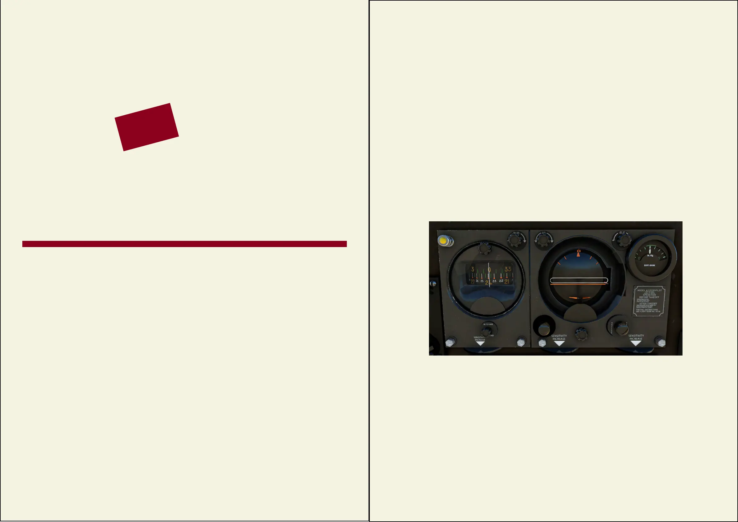
SPERRY GYRO PILOT
When you are ying long distances you
cankeepyourairplaneinstraightandlevelight
by means of the Speery Gyro Pilot. It detects
ightdeviations theinstanttheyoccurandcor-
rects them immediately and with precision. Use
this pilot only in ordinary weather conditions and
never in extremely turbulent air.
To set the Gyro-pilot in operation, trim
your airplane then:
1.Aligntheadjustableindexcard(2)withthe
gyro card (3) in the directional gyro unit.
2. Check Suction (13). It should read between
3.75” and 4.25” Hg.
3. Turn the shut-off valve control on the
hydraulic panel to the ON position.
4. Turn the Power control (1) ON
to ON or turn the automatic pilot control on
the pedestal base to ON.
5. Press the Heading Hold Button (5)
Theairplanewillbeheldinthisightpo-
sitionunlessadjusted,usingtheSperrycontrols.
If you wish to enter a climb under Gyro-
pilotorif youneedtoadjustthepitchangleof
the nose, use the knob marked “ELEV” (8) which
will adjust the pitch reference (7) . The orange
horizon bar (9) will move to maintain its position
in the center of the pitch reference bar and the
aircraft’s nose will rise (or fall). If you wish to
maintain the pitch of the aircraft, press the Pitch
Holdknob(6)Youcanstillajustthepitchusing
the ELEV (pitch reference) knob (8) If you wish
to alter your heading while under automatic pilot
control,turntheknobmarked“RUD”toadjust
the index (upper) card in the gyro. Now TURN
OFF the Heading Hold (5) The aircraft will turn
to the new heading and the index and gyro cards
will align again, to show your new heading.
NOTE: The servo controls (speed valves)
are INOP in this simulation.
1.
2.
3.
4.
5. 6.
7.
8.
9.
10.
1. Power
2. Index Card
3. Heading Gyro
4. Index Adjuster
5. Heading Hold (push)
6. Pitch Hold (push)
6. Bank indicator
7. Pitch Reference
8. Pitch Reference Adjuster
9. Pitch Indicator Bar
10. Cage Knob
11. Gyro Cage (plate)
12. Attitude Wings Adjuster
13. Suction Gauge
The Sperry Gyro Pilot is NOT
the same as the more modern
autopilotsyouwillbeusedtoinightsimulators.
It was designed in the late 1930’s as a device to
maintainanaircraft’sightattitude-thatislevel
ight and direction, once these are set bytrim-
ming.
It should be remembered that this unit is
not designed as a navigation aid and was never
meant to be one. For that, you need more modern
equipment or do as the original pilots did - rely on
dead-reckoning, sextant and VFR.
Note
28
11.
12.
13.
 Loading...