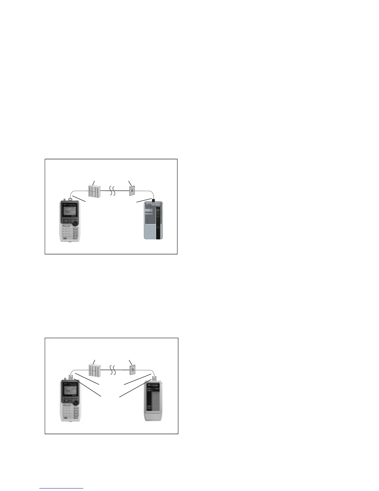
The diagram shows the connection of a
PentaScanner
+ to an IDC (110) block in the wiring closet
and a
2-Way Injector+
or
Super Injector+
to a Modular 8 jack in the work area.
Punch Down Block Adapter kits are available (as optional accessories) to interface the Scanners
with IDC (110) punch-down blocks. For the
PentaScanner+
, order kit #8123-01. For the
PentaScanner
and
PentaScanner
Cable Admin
, order kit #8051-13.
Use the 110 Block to 36-pin patch cable to attach the Scanner to the 110 Punch down block. At
the other end of the link, use the Modular 8 plug to 36-pin patch cable to attach the Injector to
the Modular 8 jack.
If you are using a 2-Way Injector or Super Injector, use the Modular 8 patch cable to connect the
Injector to the Modular 8 jack, as shown:
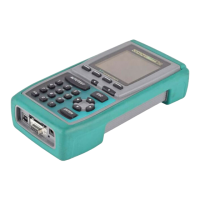
Full Channel Modular 8 Link
A full channel consists of the different link elements from the hub to the wallplate. For cables
terminated with a Modular 8 plug, use the Modular 8 Adapter to interface the PentaScanner+
with these cables. This diagram shows the connection of a
PentaScanner+
to a cross connect in the
wiring closet and a
2-Way Injector+
or
Super Injector+
to a Modular 8 jack in the work area.
Wiring Closet Work Area
Modular 8 Jack
Modular 8 Injector
36-Pin Scanner
Modular 8
Adapter
110 block
User Cable
Wiring Closet Work Area
Modular 8 Jack
110Block
to 36-Pin
Patch Cable
Modular 8 Injector
36-Pin Scanner
Modular 8
Patch
Cable
110 block