Do you have a question about the Microtest OMNIScanner2 and is the answer not in the manual?
Overview of OMNIScanner's capabilities for copper and fiber link verification and analysis.
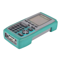
Description of OMNIScanner's display, menus, and navigation keys.
Details the function and indicators of the OMNIRemote unit.
Explains OMNIFiber's role in fiber testing and data saving.
Overview of PC-based software for managing projects, reports, and configurations.
Details display elements and navigation.
Describes the device's keypad functions.
How to initiate an autotest.
How to use the keypad for data entry.
Explains the purpose of function keys.
Meaning of OMNIRemote status lights.
When OMNIRemote is required for testing.
Viewing test results from both ends.
OMNIFiber MM status indicators.
OMNIFiber SM status indicators.
Connecting fiber adapters to OMNIScanner.
Connecting specific adapters.
Overview of editing methods.
How to get help.
Instructions on charging the OMNIScanner and OMNIRemote batteries.
Explains the project screen for workflow operations, test specs, and cable types.
Describes the process for certifying network installations using OMNIScanner.
Procedure for setting the reference for OMNIScanner and OMNIRemote for accurate measurements.
How to select projects, autotests, and cables for test result management.
Step-by-step guide to performing an autotest on twisted pair cabling.
Instructions on how to save autotest results for twisted pair cabling.
How to view detailed autotest results for twisted pair cabling.
Illustrates various connection setups for testing twisted pair cables.
Configuration for testing a full channel connection with modular 8 jacks.
How to perform permanent link autotests and their effects on measurements.
Instructions for charging the OMNIScanner and OMNIRemote batteries.
Explains the project screen for workflow operations, test specs, and cable types.
Process for certifying fiber optic cabling installations using OMNIScanner.
Procedure for setting the reference for fiber optic measurements.
How to select projects, autotests, and cables for fiber optic test management.
Steps to prepare and run a fiber optic autotest.
Steps for performing a loopback autotest using OMNIFiber Main.
How to input connections and splices and run a fiber autotest.
How to interpret and save fiber autotest results.
Overview of the setup feature for defining, editing, and presetting items.
Procedure to set the reference for OMNIScanner and OMNIRemote.
Steps to set the reference when using OMNIFiber adapters.
How to select and view details of standard autotest specifications.
How to select and identify cable types for testing.
Creating and modifying custom cables.
How to manage projects for organizing test specifications and results.
Creating and editing circuit identifiers.
How to manage saved configurations.
Customizing autotest behavior like aborting on fail or jumping to fail.
Configuring how autotests are saved.
Setting user preferences.
Formatting the MultiMediaCard.
Setting language, units, and date/number formats.
Overview of performing individual tests on various cabling types.
How to run individual tests for twisted pair cabling.
How to run individual tests for fiber optic cabling.
How to run individual tests for coaxial cabling.
Details on performing twisted pair measurements.
Tests twisted-pair cabling for wiring faults and displays length.
Measures cable length, propagation delay, and skew.
Measures Near End Crosstalk between pairs at the near end.
Measures signal loss in a cable as a function of frequency.
Measures the uniformity of a cable's impedance.
Measures electromagnetic coupling at the far end, normalized for attenuation.
Measures Attenuation to Crosstalk Ratio and usable frequency range.
Measures loop resistance in cable pairs.
Measures cumulative NEXT, considering multiple transmission pairs.
Calculates summation of individual ELFEXT effects on each pair.
Calculates cumulative ACR from Attenuation and Power Sum NEXT.
Details on performing measurements on fiber optic cables.
Details on performing measurements on coaxial cables.
Overview of diagnostic tests for identifying network cabling faults.
Identifies opens, breaks, and shorts in cables and displays length to fault.
Interpreting the graphical representation of wiremap results and fault indicators.
Diagnoses NEXT faults using Time Domain NEXT technology.
How to use TDNXT graphs and S-Bands to pinpoint connection or cable faults.
Practical TDNXT diagnostic scenarios.
Measures reflected energy in a link using Time Domain Return Loss.
How to use TDRL graphs and S-Bands to pinpoint Return Loss faults.
Practical TDRL diagnostic scenarios.
Measures electrical noise on cables.
Traces cables using an audible tone.
Identifies cable termination points in offices.
Accessing saved autotest results.
Detailed review of autotest results.
Display of twisted pair test outcomes.
Display of fiber optic test outcomes.
Managing results on external storage.
Setting up reference measurements for fiber optics.
Details on fiber optic test cables.
Procedure for the one-jumper reference method.
Procedure for the two-jumper reference method.
Procedure for the three-jumper reference method.
Procedure for loopback mode reference.
Overview of Scanlink software suite.
Steps to download software updates from the Microtest website.
Process for updating device software.
Using MultiMediaCards for data storage and transfer.
Procedures for formatting and maintaining MultiMediaCards.
Step-by-step instructions for installing the USB driver on a PC.
How to transfer test results from OMNIScanner2 to a PC using Scanlink.
How to download configurations from PC software to OMNIScanner2.
How to control OMNIScanner2 remotely from a PC.
Device dimensions and weight.
Device display and keypad details.
OMNIRemote status indicators.
OMNIFiber MM status indicators.
OMNIFiber SM status indicators.
Battery and power specifications.
Operating conditions.
Test interface details.
Serial port specifications.
USB connection details.
MMC interface details.
Memory capabilities.
List of autotest types.
List of core measurement functions.
Method for performance measurements.
Accuracy specifications.
Safety feature description.
Information on the rechargeable, recyclable battery packs and their disposal.
Procedures and status indicators for charging the batteries.
Advice for battery maintenance.
Pin-out configuration for a DB-9 male to DB-9 female serial cable.
Pin-out configuration for a DB-9 male to DB-25 female serial cable.
Signal descriptions for cable pins.