Do you have a question about the Midas 502 and is the answer not in the manual?
General precautions for preventing fire, electric shock, ensuring ventilation, and proper grounding.
Guidelines for cord protection, accessory use, moving equipment, servicing, and environmental considerations.
Warnings about uninsulated voltage and prohibition of opening the unit to prevent electric shock.
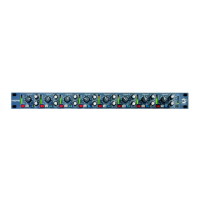
Secures the 502 module into the 500 series rack chassis using screws.
Precision 11-segment meter showing post-preamp, pre-filter signal for gain setting.
12-position rotary switch for mic/line gain from 0 to +60 dB, handling high input levels.
Activates +48V phantom power for microphones; LED indicates status.
Adjusts low-pass filter frequency from 1 kHz to 40 kHz to remove HF noise or add vintage sound.
Inserts the low-pass filter into the signal path; yellow LED indicates activation.
Reverses signal phase by 180 degrees; green LED indicates status.
Adjusts high-pass filter frequency from 10 Hz to 400 Hz to remove unwanted low frequencies.
Inserts the high-pass filter into the signal path; yellow LED indicates activation.
Switches between standard balanced output and transformer-balanced output for vintage sound.
Precision 11-segment meter showing output signal level for trim control setting.
Provides +/- 20 dB output level control for precise gain staging and coloration.
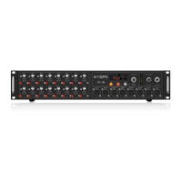
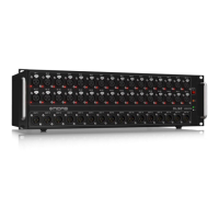
Mounts the 502 module into a 500 series rack chassis and secures it with screws.
Fills empty slots in the rack chassis to prevent dust and objects from entering.
Inserts other modules into the system after the 502 module is installed.
Connects microphones and other audio gear to the rack chassis inputs and outputs.
Provides +48V phantom power to microphones, with caution advised for compatible devices.
Turns on the rack unit, featuring a 2-second delay to prevent power-on thumps.
Details of phantom power, gain control, filters, and output type settings.
Specifies input/output impedance, signal type, and CMRR.
Lists noise levels at unity gain and frequency response for electronic/transformer outputs.
Provides distortion figures and low/high pass filter characteristics.
Describes meter types and power consumption/voltage requirements.
Outlines the physical size and weight of the module.
Encourages registering the product online for faster repair claims and warranty information.
Provides guidance on contacting support or using online resources for troubleshooting.
Advises on using the correct mains voltage and replacing fuses with identical types.