8 MIDA S DL16 User Manual 9 MIDA S DL16 User Manual
4. Conguring the DL16
By using the CONFIG button and SELECT/ADJUST knob, the DL16 can be congured
to suit many dierent applications. The STATUS LEDs indicate the current settings.
By holding the CONFIG knob while turning the SELECT/ADJUST knob, you can
scroll through all 10 conguration options. See the Operation Mode Chart for the
routing details of each conguration setting.
When using multiple DL16 units, activating SN(ake) MASTER mode on one unit
allows that unit to control the preamp gain of the second unit. An DL16 set to
SN MASTER will also dictate the overall clock synchronization (44.1 or 48 kHz).
Thisis useful when using a pair of DL16s as a standalone digital snake (16 x 16)
ora 32-channel mic preamp via ADAT. See the ’Standalone Operation’ section
fordetails.
SPLITTER mode routes the 16 local analog inputs directly to the ADAT outputs
and ULTRANET output. This is useful when using the DL16 as a standalone snake
where the ULTRANET monitor mix cannot be adjusted from an M32 console.
Additionally, the DL16 can be used as a high-quality mic preamp that sends the
16 inputs to an interface or computer with an ADAT card for recording purposes.
When SPLITTER mode is o, the ADAT outputs carry AES50 channels 17-32 and the
ULTRANET output carries channels 33-48.
The OUT +8 and OUT +16 options shift the XLR outputs for use with
multiple DL16s. For example, if a connection scenario involves 3 daisy-chained
DL16s, therstunit will carry AES50 channels 1-8. The second unit should be set
to OUT+8 so that its analog outputs carry channels 9-16, and the 3rd DL16 should
be set to OUT+16 so that its analog outputs carry channels 17-24. This way you
can provide up to 24 return signals to the stage. Alternatively, you may also use
the same block of 8 output signals on a set of distributed DL16 stageboxes.
MIDAS DL16 Operation Mode Chart
Seq.
LED
SN MASTER
sync clock
LED
SPLITTER
LED
OUT +16
LED
OUT +8
XLR analog
out 1-8
ADAT
out 1-8
ADAT
out 9-16
P-16 Ultranet
out 1-16
1 (default) AES50 (console)
= AES50-A,
ch01-ch08
= AES50-A
ch17-ch24
= AES50-A
ch25-ch32
= AES50-A
ch33-ch48
2 AES50 (console) on
= AES50-A
ch09-ch16
= AES50-A
ch17-ch24
= AES50-A
ch25-ch32
= AES50-A
ch33-ch48
3 AES50 (console) on
= AES50-A
ch17-ch24
= AES50-A
ch17-ch24
= AES50-A
ch25-ch32
= AES50-A
ch33-ch48
4 AES50 (console) on
= AES50-A,
ch01-ch08
= Local In
01 - 08
= Local In
09 - 16
= Local In
01 - 16
5 AES50 (console) on on
= AES50-A
ch09-ch16
= Local In
01 - 08
= Local In
09 - 16
= Local In
01 - 16
6 AES50 (console) on on
= AES50-A
ch17-ch24
= Local In
01 - 08
= Local In
09 - 16
= Local In
01 - 16
7 on 48 kHz (int)
= AES50-A,
ch01-ch08
= AES50-A,
ch01-ch08
= AES50-A
ch09-ch16
= AES50-A
ch01-ch16
8 on 44.1 kHz (int)
= AES50-A,
ch01-ch08
= AES50-A,
ch01-ch08
= AES50-A
ch09-ch16
= AES50-A
ch01-ch16
9 on 48 kHz (int) on
= AES50-A,
ch01-ch08
= Local In
01 - 08
= Local In
09 - 16
= Local In
01 - 16
10 on 44.1 kHz (int) on
= AES50-A,
ch01-ch08
= Local In
01 - 08
= Local In
09 - 16
= Local In
01 - 16
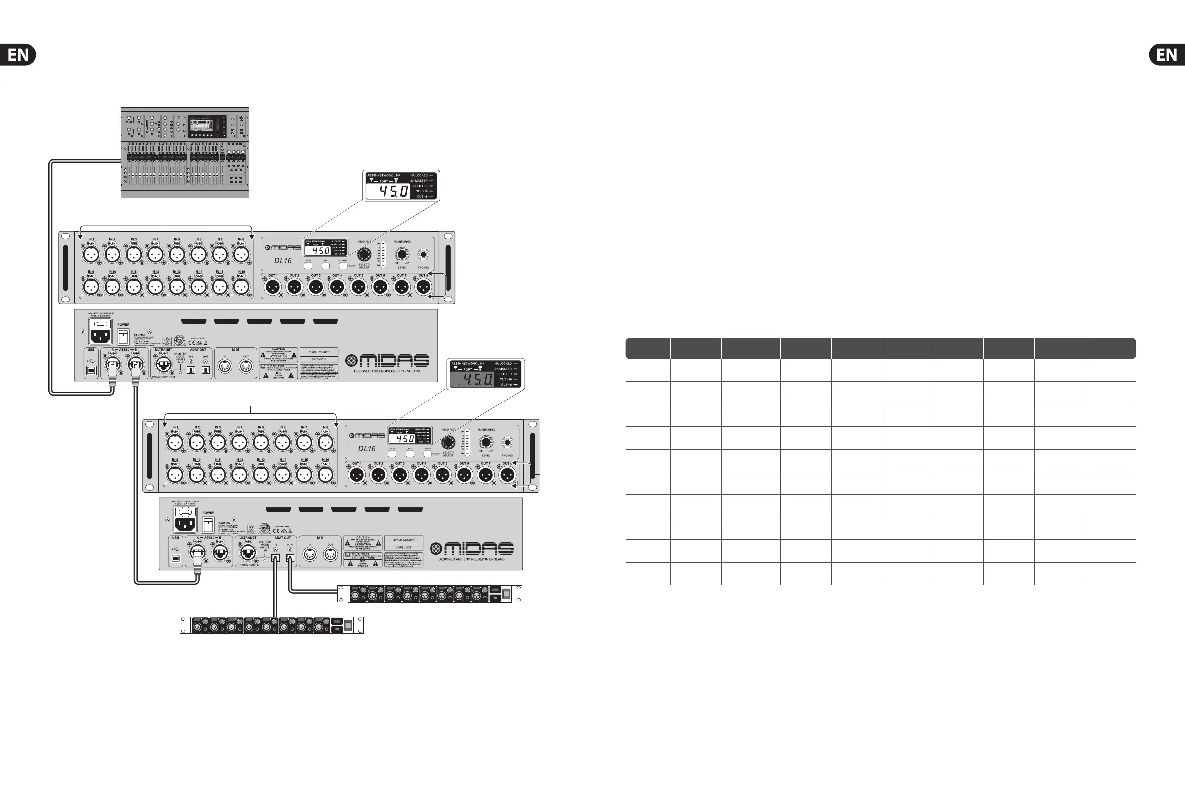
Linking two DL16 units
IN 1-16
OUT 17-24
OUT 25-32
ADA8200
ADA8200
OUT 1-8
OUT 9-16
IN 17-32
M32
Note: The signals on both DL16 units (Out 1-8 and 9-16) and both ADA8200 units (Out 17-24 and 25-32)
are fully dened on the M32’s ’Routing/AES50 Output’ page. The second DL16’s outputs must be set to
Out+8on the unit itself.
 Loading...