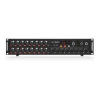
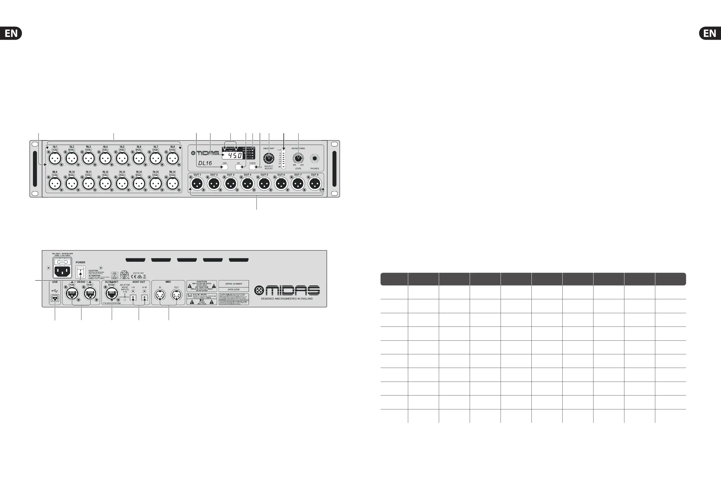
(7) STATUS LEDs show the operation mode
of various features. See the Operation
ModeChart for details. The HA LOCKED LED
indicates that preamp gain adjustment
has been blocked by the controlling M32.
To unlock, open the M32 Setup/Global
page and un-check the General Preference
’LockStagebox’.
(8) CONFIG button, when pressed and held,
allowsthe device’s operation mode to
be adjusted by the SELECT/ADJUST knob.
SeeOperation Mode Chart for details.
(9) SELECT/ADJUST knob scrolls through the
16channels, adjusts the gain of the currently
selected input, and changes the operating
mode. Push repeatedly to scroll Inputs,
Outputs, P16 channels, ADAT outputs,
andStage (onlyinSnakeMaster mode).
(10) LED METER displays the signal level of the
currently selected channel.
(11) MONITORING LEVEL knob adjusts the level of
the PHONES output.
(12) XLR outputs accept balanced XLR
female plugs.
(13) POWER switch turns the unit on and o .
(14) USB input accepts a USB type-B plug for
rmware updates via PC.
(15) AES50 ports allow connection to a SuperMAC
digital multichannel audio network via
shielded Cat-5e Ethernet cable with
terminated ends. This allows connection
to digital mixers or cascading of multiple
DL16units.
(16) ULTRANET port sends 16 channels to a
Behringer P-16 personal monitoring system.
(17) ADAT OUT jacks send AES50 channels
17-32 to external equipment via optical
cable, or split the local 16 inputs for direct
ADAT recording.
(18) MIDI IN/OUT jacks accept standard 5-pin
MIDI cables for MIDI communication to and
from an M32 console.
Step 2: Controls
(1) PHANTOM LEDs light when the 48V button is
engaged for a particular channel.
(2) MIDAS PRO mic/line inputs accept balanced
XLR male plugs.
(3) GAIN button, when pressed and held,
displaysthe currently selected mic input’s
gain setting, which may then be adjusted
using the SELECT/ADJUST knob.
(4) DISPLAY shows the selected channel number,
its gain setting, or the sample rate in
SnakeMaster con guration.
(5) NETWORK LINK LEDs light red to indicate
the AES50 ports are connected but not
synchronised, and light green to indicate
theyare connected and synchronised.
(6) 48 V button sends phantom power to the
currently selected mic input, indicated by a
litbutton when active.
MIDAS DL16 Operation Mode Chart
Seq.
LED
SN MASTER
sync clock
LED
SPLITTER
LED
OUT +16
LED
OUT +8
XLR analogue
out 1-8
ADAT
out 1-8
ADAT
out 9-16
P-16 Ultranet
out 1-16
1 (default)
AES50
(console)
= AES50-A,
ch01-ch08
= AES50-A
ch17-ch24
= AES50-A
ch25-ch32
= AES50-A
ch33-ch48
2
AES50
(console)
on
= AES50-A
ch09-ch16
= AES50-A
ch17-ch24
= AES50-A
ch25-ch32
= AES50-A
ch33-ch48
3
AES50
(console)
on
= AES50-A
ch17-ch24
= AES50-A
ch17-ch24
= AES50-A
ch25-ch32
= AES50-A
ch33-ch48
4
AES50
(console)
on
= AES50-A,
ch01-ch08
= Local In
01 - 08
= Local In
09 - 16
= Local In
01 - 16
5
AES50
(console)
on on
= AES50-A
ch09-ch16
= Local In
01 - 08
= Local In
09 - 16
= Local In
01 - 16
6
AES50
(console)
on on
= AES50-A
ch17-ch24
= Local In
01 - 08
= Local In
09 - 16
= Local In
01 - 16
7 on 48 kHz (int)
= AES50-A,
ch01-ch08
= AES50-A,
ch01-ch08
= AES50-A
ch09-ch16
= AES50-A
ch01-ch16
8 on 44.1 kHz (int)
= AES50-A,
ch01-ch08
= AES50-A,
ch01-ch08
= AES50-A
ch09-ch16
= AES50-A
ch01-ch16
9 on 48 kHz (int) on
= AES50-A,
ch01-ch08
= Local In
01 - 08
= Local In
09 - 16
= Local In
01 - 16
10 on 44.1 kHz (int) on
= AES50-A,
ch01-ch08
= Local In
01 - 08
= Local In
09 - 16
= Local In
01 - 16