ENGLISH
9
IV. THERMOCOUPLE INSTALLATION
1. Install one thermocouple sensing bulb into each of the two
holes in the rear panel of the oven, as shown in Figure 2-4.
Fasten each thermocouple in place using one of the #10-
32 x 3/8" screws supplied in the Installation Kit.
2. Thread BOTH sets of thermocouple leads through the
grommet and into the machinery compartment, as shown
in Figure 2-4.
3. Remove the right-side access panel of the machinery
compartment.
4. Thread the thermocouple leads through the side of the
machinery compartment as shown in Figure 2-5, and into
the electrical box (at the right-front of the machinery compart-
ment).
5. Connect BOTH sets of thermocouple leads to the tempera-
ture controller as shown in Figure 2-6. Note that the two
thermocouples are now tied together at the temperature
controller.
6. Replace the right-side panel of the machinery compart-
ment.
7. Repeat Steps 1-6 for any other oven cavities in the installa-
tion.
8=White=Positive
7=Red=Negative
R=No Connection
Ground=Shielded cable
Figure 2-4 - Thermocouple Installation Locations
Figure 2-5 - Placing the Thermocouple Leads
Figure 2-6 - Thermocouple Lead Connections
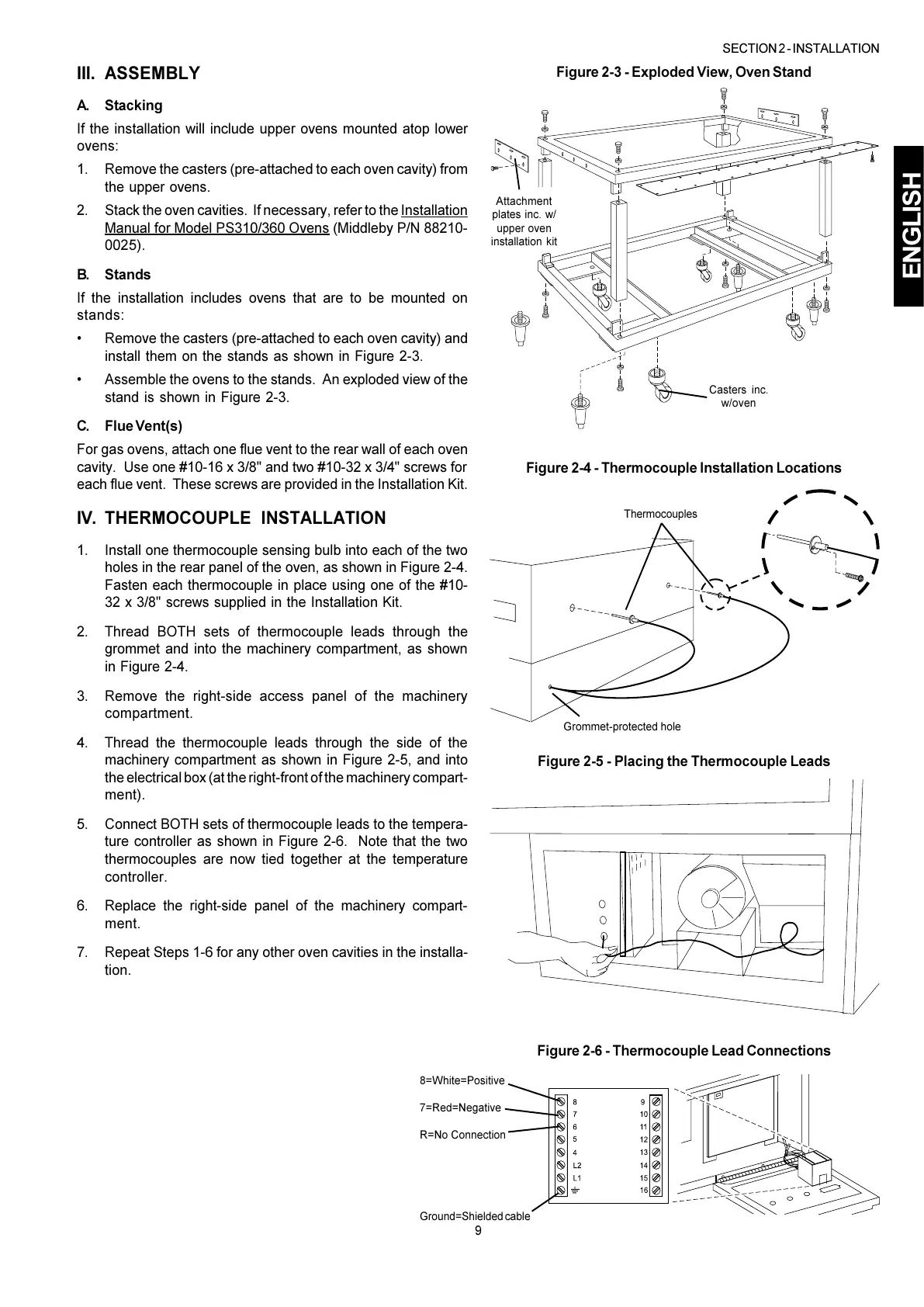
III. ASSEMBLY
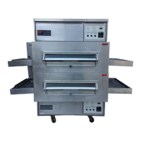
A. Stacking
If the installation will include upper ovens mounted atop lower
ovens:
1. Remove the casters (pre-attached to each oven cavity) from
the upper ovens.
2. Stack the oven cavities. If necessary, refer to the Installation
Manual for Model PS310/360 Ovens (Middleby P/N 88210-
0025).
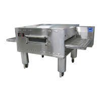
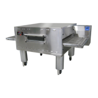
B. Stands
If the installation includes ovens that are to be mounted on
stands:
Remove the casters (pre-attached to each oven cavity) and
install them on the stands as shown in Figure 2-3.
Assemble the ovens to the stands. An exploded view of the
stand is shown in Figure 2-3.
C. Flue Vent(s)
For gas ovens, attach one flue vent to the rear wall of each oven
cavity. Use one #10-16 x 3/8" and two #10-32 x 3/4" screws for
each flue vent. These screws are provided in the Installation Kit.
Figure 2-3 - Exploded View, Oven Stand
Attachment
plates inc. w/
upper oven
installation kit
SECTION 2 - INSTALLATION
Casters inc.
w/oven
Thermocouples
Grommet-protected hole
 Loading...